DM422T Digital Stepper Drive User Manual
3.3 LED Light Indication
There are two LED lights for DM422T. The GREEN one is the power indicator which will be always on
generally. The RED one is a protection indicator which will flash 1-2 times in a 3-second period, when
protection enabled for a DM422T. Different number of flashes indicates different protection type (read section
8 for detail).
4. Control Signal and Output Signal
4.1 Control Signal Connection
It is recommended adding an EMI line filter between the power supply and the drive to increase noise
immunity for the drive in interference environments.
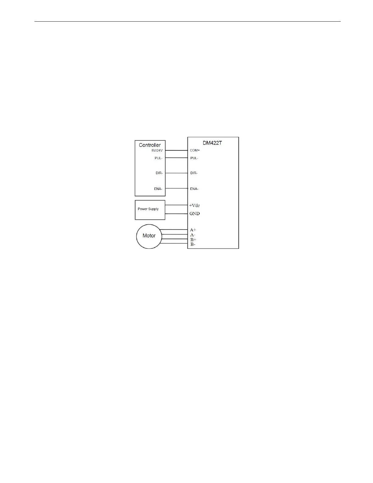
Figure 4: Typical Connections
Notes:
(1) ENA signal is no-connected as default;
(2) Control signal amplitude is 24 V as default. If it is 12 V, please set dip switch to 5 V first, then connect 1KΩ
resistor; if it is 5V, please set to 5V.
(3) The ports of DM422T are not compatible with the controllers with common cathode ports (STEP, DIR, ENA,
GND)
4.2 Alarm Output Connection
When over voltage or over current protection happens, DM422T red status LED light will blink and the
impedance state between ALM+ and ALM- will change (from low to high or high to low depending on
configuration) and can thus be detected. Fault output connection is optional, and it can be connected either in
sinking or sourcing.