
A
audrey30Aug 5, 2025
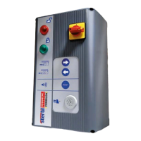
What to do if there is no control voltage in Stertil Trucks?
- CcharlesfritzAug 5, 2025
If there is no control voltage in your Stertil Trucks appliance, try the following: * First, press the 'reset alarm' button once, as the control voltage might not be switched on yet. * Check if the emergency-push button is pressed in. If it is, unlock it in the direction of the arrow and then press the reset alarm button once. * Ensure the keyboard is functioning by checking the internal plug connection. * See if the automatic fuse has been activated. If so, reset the fuse by switching off and on the main switch. If the problem returns, alert the service department. * Finally, verify if the fuse is defective and replace fuse F1 (630 mAT), see FIG. D.