24
6. LIST OF PARTS AND FIGURES
6.1 LIST OF PARTS
Explanation of numering of the list of parts
The list of parts and drawings are subdivided into the following groups:
FIG. A
ASSEMBLY COMBILOK
FIG. B
ASSEMBLY CROSS-HEAD
FIG. C
ASSEMBLY HYDRAULIC CYLINDERS “A” AND “B”
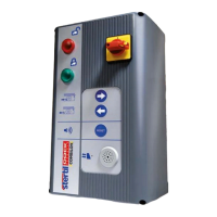
FIG. D
CONTROL BOX
FIG. E
ASSEMBLY ELECTRIC
FIG. F
ASSEMBLY HYDRAULIC
FIG.
G
ELECTRIC DIAGRAM
FIG. H
CABLE CONNECTIONS
FIG. I
HYDRAULIC DIAGRAM
FIG. J
HYDRAULIC UNIT
FIG. K
FOUNDATION INSTRUCTION (RIGHT MODEL)
FIG. L
FOUNDATION INSTRUCTION (LEFT MODEL)
The titles of the columns in the list of parts have the following meaning:
Index Index indicates to parts of this drawing.
Reference Numbers in this column are STERTIL order numbers.
Please state these numbers when making orders.
Description This column comprises the names of the parts.
6.2 ORDERING REPLACEMENT PARTS
The following should be indicated when making orders:
Type : Combilok
Serial no. : See front, or type plate
Reference no. : See fig. FIG. A - FIG. L.
Only use genuine Stertil parts!