17
2. OPERATION
2.1 GENERAL
The Combilok should only be used for locking vehicles that are loaded and discharged from the rear side on a
loading/discharging platform.
The Combilok may only be operated by personnel appointed by the company management.
The Combilok prevents vehicles from rolling forward. It is possible (in the event of a small load and/or sufficient
drive torque from the vehicle) to drive over the wheel block. Under normal circumstances the driver will find that
there is sufficient resistance against the vehicle rolling back.
Under normal usage conditions the Combilok offers sufficient protection against (premature) moving off or
gradual rolling back of vehicles.
The device has a preventative function against theft attempts. However, it is not intended as protection against theft.
In the event of a malfunction, or when the activities have been completed, the main switch must be put into the 0
position. It is only possible to render the Combilok voltage-free by switching off the main switch.
2.2 OPERATING INSTRUCTIONS
To gain a better understanding of the locking system see para 1.8. Read the general instructions in para 2.1. first.
Vehicles should be docked (with open rear doors) on the rear side. In order to avoid wearing out the fender rubbers
on the vehicles and/or the platform, some space can be left between the vehicle and the leveller. It is advisable to
use moveable bumpers on the dock to minimize wear of the bumpers. According to normal procedure, the parking
brake of the truck is engaged.
The free space for the rear wheels must be 400 mm in height and 250 mm in length. This space is needed for
pushing the block in. If this clearance is not provided for, the transverse movement slide-out piece will jam. Then,
an operating time control facility ensures that the Combilok takes up the alarm position.
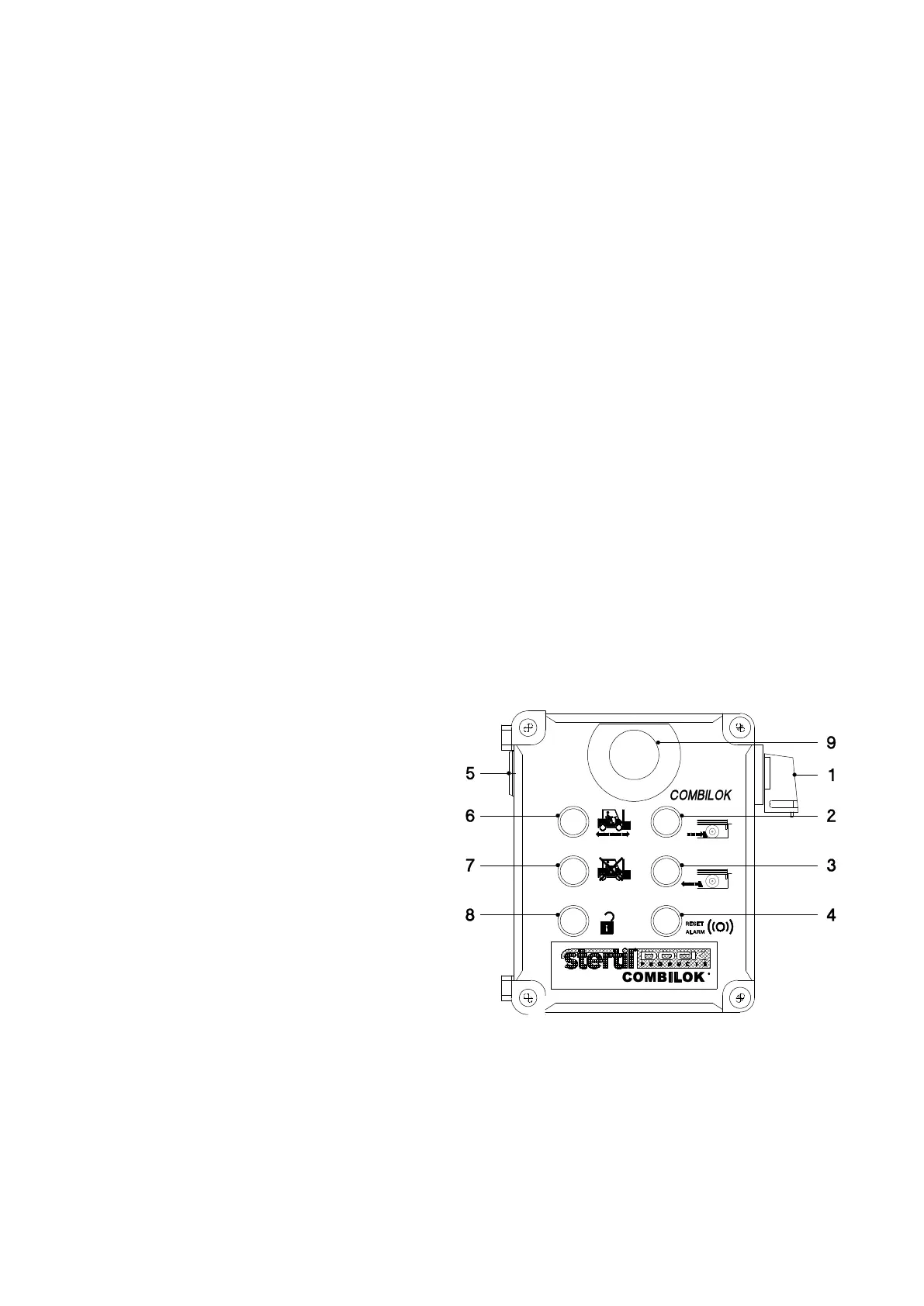
Operation of the Combilok takes place inside the building (see control panel fig. 2A). Because there is no overview
of the vehicle to be locked, a choice has been made for an automatically operating system.
The mains voltage is passed to the system when the main switch is turned to position I. The control voltage is
switched on by pressing button 4 'control voltage' once.
1. Main switch
2. Lock vehicle
3. Release vehicle
4. Alarm off/control voltage in
5. Alarm beeper
6. Lamp green loading/unloading
7. Lamp red loading/unloading forbidden
8. Lamp yellow release for dock leveller
9. Emergency stop
Fig. 2A, Control panel