INSTALLATION
Service information
12 | DCE-S Plus www.stiebel-eltron.com
1.
2.
3.
4.
D0000077974
1 2 3
4
5
1 Flow limiter
2 O-ring
3 Cold water pipe bend with recess for spring clip
4 Spring clip
5 Heater
f Remove the cold water pipe bend and the O-ring.
f Insert the flow limiter (part of the appliance standard deliv-
ery) in the cold water inlet of the heater. Note the orientation.
f Fit the cold water pipe bend with the O-ring.
!
Material losses
The O-ring must be fitted to prevent the appliance from
leaking.
f As part of installation, check that the O-ring is in
place.
f Secure the cold water pipe bend with the spring clip.
!
Material losses
Ensure that the spring clip is located behind the recess
in the pipe bend and that it is securely holding the pipe
bend in place.
f Fit the function module on the appliance back panel in re-
verse order until it clicks into place.
f Secure the function module with the screw.
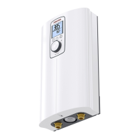
Installing the appliance
D0000073842
321
1 Grommets
2 Flat gasket
3 Strainer with sealed edge
f Mark out the 2drilling positions in the upper section of the
appliance back panel with reference to the appliance back
panel.
f Fit the grommets in the appliance back panel from the front.
f Drill the holes and secure the appliance using suitable fixing
materials (screws and rawl plugs are not part of the standard
delivery): Countersunk screw, Ø4.5mm, max. diameter of
screw-head 9mm.
Note
f Install the appliance flush to the wall. If necessary,
additionally secure the appliance at the 2 lower
attachment points. To do this, push/break out the
lower slots (175mm apart) in the appliance back
panel (for positions, see chapter "Specification/ Di-
mensions and connections").
f Remove the transport protection plugs from the water con-
nection pipes.
f Secure the DHW connection pipe with a flat gasket and the
cold water inlet line with the sealed-edge strainer (from the
accessories) to the twin connectors.
12.6 Operation with preheated water
You can limit the maximum inlet temperature by installing a cen-
tral thermostatic valve.
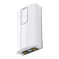
13. Service information
Connection overview/ component overview
D0000082950
1
2
3
4
5
6
1 Flow meter
2 High limit safety cut-out, automatic reset
3 NTC sensor
4 Pin strips for connected load and anti-scalding protection
5 Programming unit plug-in position
6 Diagnostic traffic lights

 Loading...