25
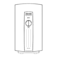
Water connection
DHC 3 U, DHC 6 U
An example of installation with
conventional pressure fitting (Fig. 10).
Items to be provided by client:
1 Blender fitting for sink
2 Copper pipe ∅ 10 mm
3 Angle valve
4 T-piece
– Establish water connection (use
compression fittings provided, Item 5).
– Connect jet regulator unit, Item 6 (only
DHC 3 U, enclosed) to the fitting
outlet.
Fig. 12
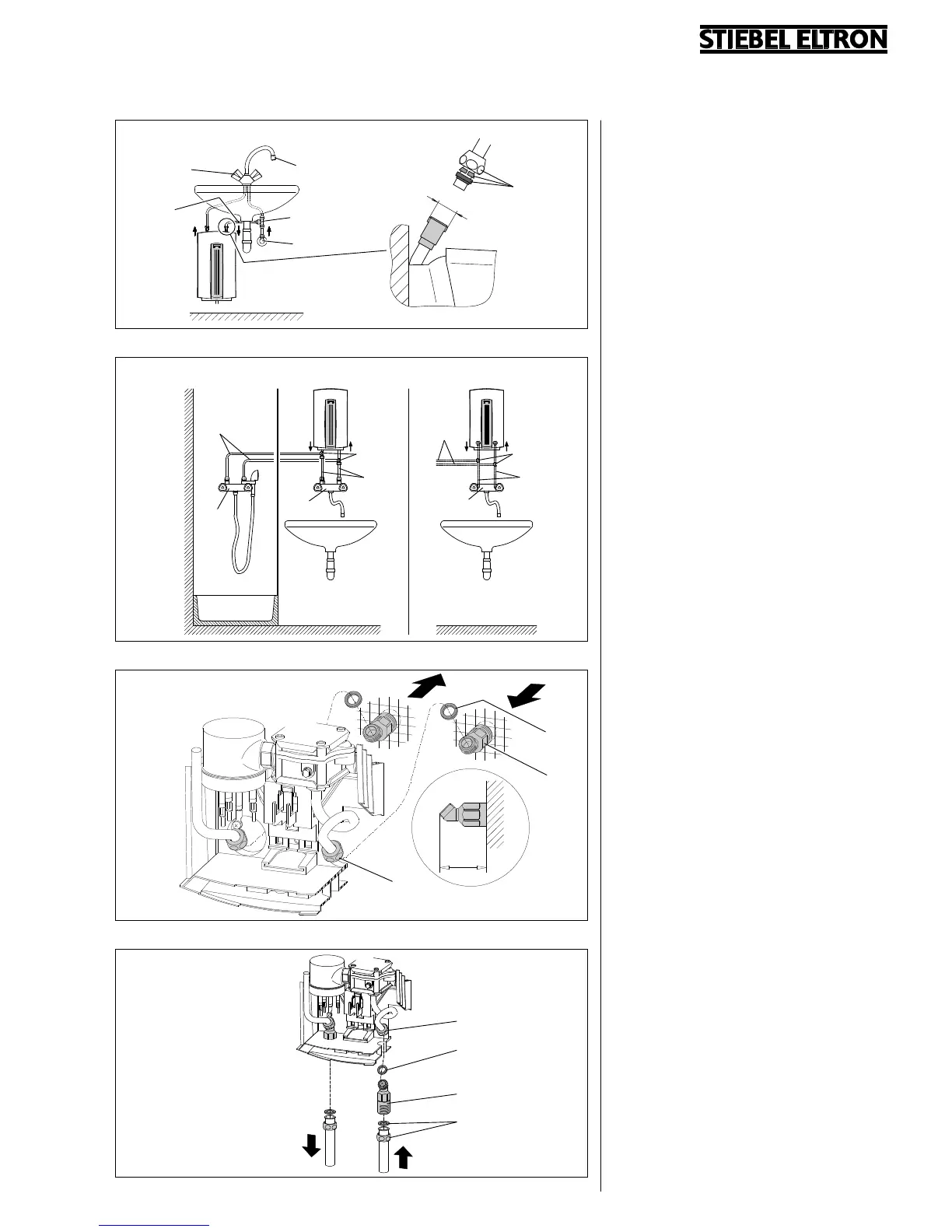
Fig. 11
7053.01
WW KW
DHC 3, DHC 4, DHC 6, DHC 8
DHC 3, DHC 4,
DHC 6, DHC 8
DHC 3, DHC 4,
DHC 6, DHC 8
7052.02
min. 46
max. 50
mm
DHC 3 U, DHC 6 U
Fig. 10
7051.01
7066.02
1
6
2
4
3
G 3/8
7054.01
Fig. 13
WW
KW
10 T-piece
Concealed connection (Fig. 12)
– Screw the unit connection nipple
(Item 11) to the water installation (cold
water and hot water; pay attention to
position and installation depth).
– With the connection apertures broken
through, guide the unit over the
connection nipples on the installation
wall.
– Screw the union nut (Item 12) of the
pipe bend (cold water and hot water)
with the gasket (Item 13) onto the
connection nipple.
Connection above work surface
(Fig. 13)
– Guide the connection nipple (Item 14)
through the break-through points on
the rear wall of the unit, and screw the
union nut onto it with the gasket
(Item 15) at the pipe bend (Item 16).
– Connect surface-mounted installation
(Item 17).
11
13
12
16
15
14
17
5
8
8
7
9
9
9
10
9
10
DHC 3, DHC 4, DHC 6, DHC 8
Examples of installations with
conventional pressure fitting (Fig. 11).
Items to be provided by client:
7 Blender fitting for shower
8 Blender fitting for sink
9 Copper pipe
 Loading...