10 | WPL E | WPL COOL WWW.STIEBEL-ELTRON.COM
INSTALLATION
PREPARATIONS
9.3.2 Internal installation
1 2 3 54
26�03�01�1466
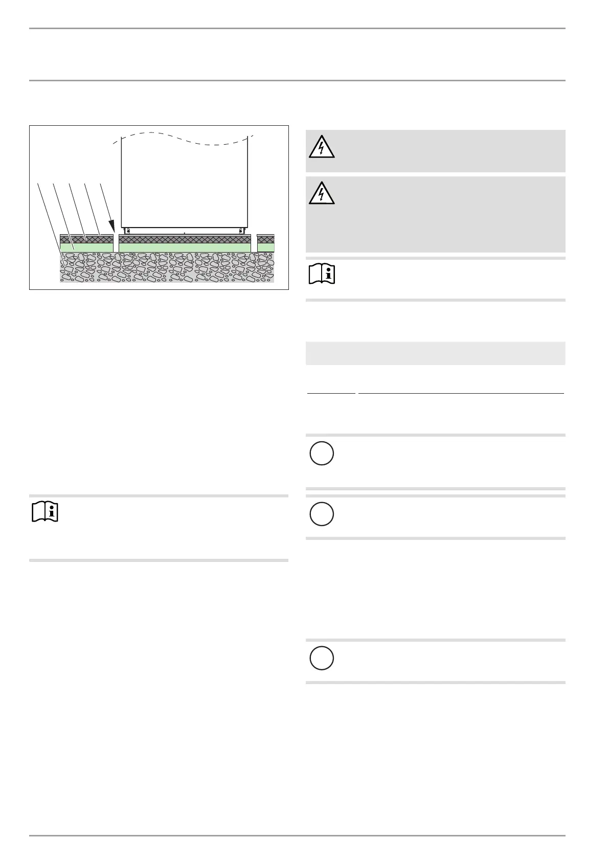
1 Concrete base
2 Impact sound insulation
3 Floating screed
4 Floor covering
5 Recess
Isolate the mounting surface around the heat pump by re-
cesses. After completing the installation, seal these recesses
with a water-impervious and sound insulating material, such
as silicone for example.
Observe the following information:
- Connect the heating circuit flow and return lines via flexible
pressure hoses. Suitable pressure hoses are listed in chapter
"Appliance description / Required accessories for internal
installation".
- Protect all pipe fixings and wall transitions with anti-vibra-
tion insulation.
Note
For details of the dimensions and positions of the air
intake and discharge apertures, as well as the outlets for
hydraulic lines and power cables, see chapter "Specifica-
tion / Dimensions and connections / Internal installation".
9.4 Electrical installation
DANGER Electrocution
Carry out all electrical connection and installation work
in accordance with national and regional regulations.
DANGER Electrocution
Only use a permanent connection to the power supply.
The appliance must be able to be separated from the
power supply by an isolator that disconnects all poles
with at least 3 mm contact separation. This requirement
can be met by contactors, circuit breakers, fuses etc.
Note
The specified voltage must match the mains voltage. Ob-
serve the type plate.
Route cables with the following cross-sections in accordance with
the respective fuse rating:
Fuse protec-
tion
Conductor cross-section
16 A
2.5 mm²
1.5 mm² with only two live wires and routing on a wall or in
an electrical conduit on a wall.
The electrical data is given in the "Specification" chapter. The BUS
cable requires a cable J-Y (St) 2x2x0.8mm².
!
Damage to the appliance and environment
Provide separate fuses/MCBs for the 3 power circuits of
the appliance, the control unit and the electricemer-
gency/booster heater.
!
Damage to the appliance and environment
Provide common fuses/MCBs for the control cable of the
appliance and the heat pump manager.
9.5 Buffer cylinder
A buffer cylinder is recommended to ensure trouble-free appli-
ance operation.
The buffer cylinder is not only installed to provide hydraulic sepa-
ration of the flow rates in the heat pump circuit and the heating
circuit, but also as an energy source for defrosting.
!
Damage to the appliance and environment
A buffer cylinder with diffusion-proof insulation is es-
sential for cooling mode.

 Loading...


