20 | WPL E | WPL COOL WWW.STIEBEL-ELTRON.COM
INSTALLATION
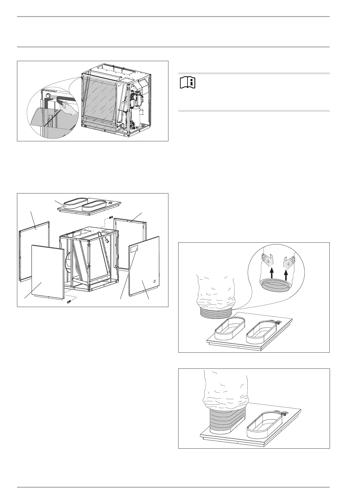
FITTING CASING COMPONENTS
26�03�01�1455
Remove the backing from the adhesive strips on the frame
and on the plastic film.
Secure the plastic film by pressing it onto the appliance.
Seal the gaps around the hooks with fabric tape.
12.2.2 Fitting casing components
2
1
3
1
5
4
26�03�01�1443
1 Side panel
2 Cover
3 Front panel
4 Type plate
5 Back panel
Place the hood on the appliance and secure with two screws.
Hook the side panels, front panel and back panel into the
hooks on the standard appliance. Secure the casing sections
with one screw each.
Affix the type plate supplied in a highly visible position on
one of the casing panels of the appliance.
12.3 Routing air hoses
Note
Air hoses guide the intake air to the appliance and route
the discharge air from the appliance to the outdoors.
They are highly flexible, thermally insulated and self-
extinguishing in case of fire.
12.3.1 General information
The air hose can be extended by turning the Bowden cores into
each other. There must be an overlap of approx.30 cm. The total
length of the hoses on the air intake and discharge sides must
not exceed 8m.
Never incorporate more than four 90° bends. The radius of
the bends must be at least 600mm, relative to the centre of
the hose.
Cut to size using a sharp knife. The Bowden core can be cut
with wire cutters.
Secure the air hose approx. every1m to prevent it sagging.
Manipulate the ends of the air hoses to fit the oval shape of
the connectors on the cover and the hose connection plates
or wall outlets.
12.3.2 Fitting air hoses
26�03�01�1446
Firstly, push the outer hose slightly upwards.
26�03�01�1447
Push the inner hose halfway down the connector.

 Loading...


