12 | WPL E | WPL COOL WWW.STIEBEL-ELTRON.COM
INSTALLATION
APPLIANCE INSTALLATION
10.2.2 Internal installation
Position the standard unit on the prepared substrate.
Pay attention to the air discharge direction.
Place the casing cover on the appliance and secure with two
screws.
5
4
3
6
26�03�01�0170
2
1
1 "Heating flow" connection
2 "Heating return" connection
3 BUS cable
4 Control cable
5 Electric emergency/booster heater power cable
6 Appliance power cable
In the cover, cut out the pipe outlets for the "heating flow"
and "heating return" connections.
Route the pressure hoses from above through the cover and
into the appliance.
Route the electrical cables from above through the cable en-
tries and into the appliance.
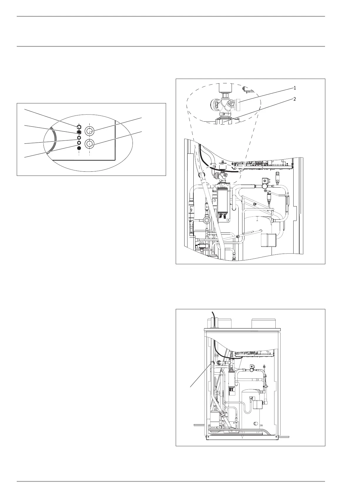
With the internal installation, rotate the connector for the "heating
flow" connection through approx.145°.
26�03�01�0947�
1
2
1 Connector
2 Union nut
Loosen the union nut.
Rotate the connector.
Retighten the union nut.
26�03�01�0173�
1
1 Pipe bend for heating circuit return
Fit the "heating circuit return" pipe bend.

 Loading...


