18 | WPL E | WPL COOL WWW.STIEBEL-ELTRON.COM
INSTALLATION
ELECTRICAL CONNECTION
X3
PE
1
2
26�03�01�0948
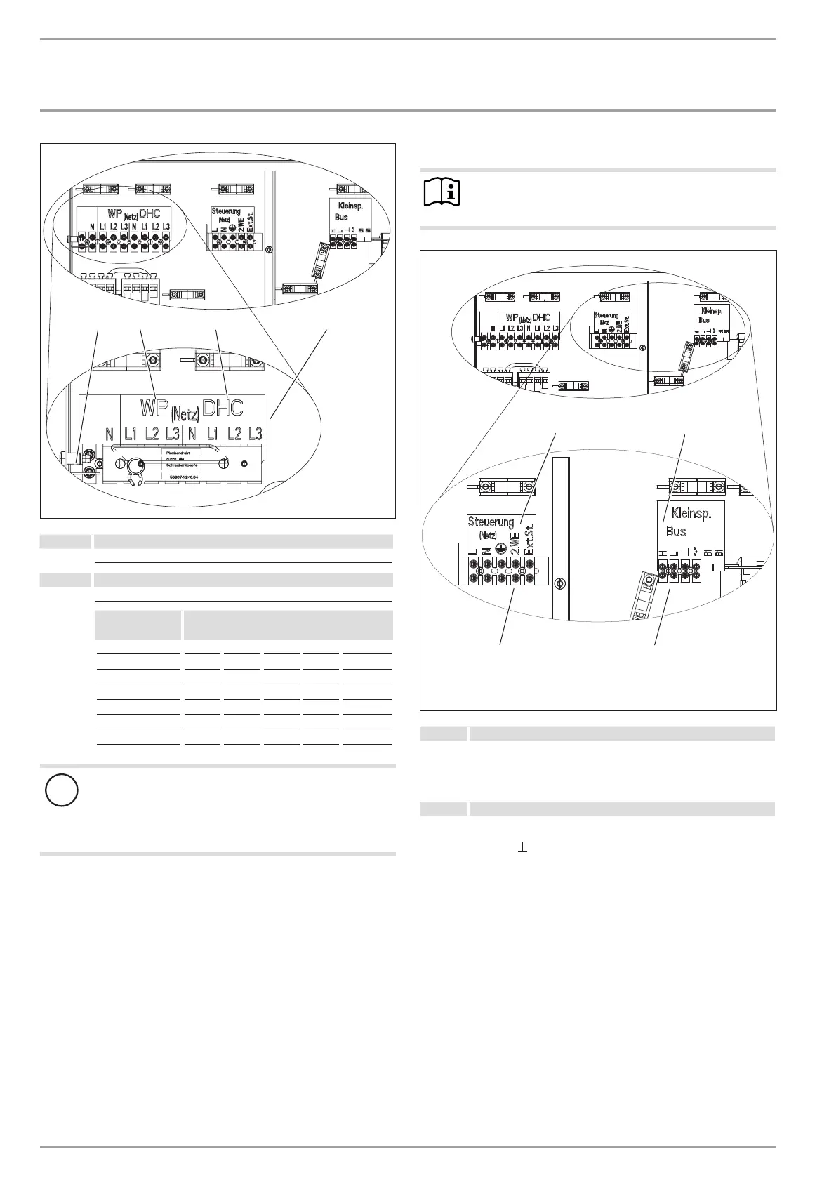
1 Heat pump power supply ("WP")
L1, L2, L3, N, PE
2 Electric emergency/booster heater ("DHC")
L1, L2, L3, N, PE
Connected
load
Terminal assignment
2.6 kW L1 N PE
3.0 kW L2 N PE
3.2 kW L3 N PE
5.6 kW L1 L2 N PE
5.8 kW L1 L3 N PE
6.2 kW L2 L3 N PE
8.8 kW L1 L2 L3 N PE
!
Damage to the appliance and environment
The compressor in the appliance can only turn in one
direction. If the appliance is not connected correctly, the
compressor remains in operation for 30 seconds then
switches off.
On the heat pump manager display, the fault message
NO OUTPUT
appears.
To change the direction of the rotating field, when the power
is disconnected, swap over two phases.
Cover and seal the mains terminal (X3) when all electric ca-
bles have been connected.
Connections X4, X2: Control unit and low voltage
Note
Provide common fuses/MCBs for the control cable of the
appliance and the heat pump manager.
26�03�01�0949�
1
2
X2
X4
1 Control unit ("Steuerung")
Power supply: L, N, PE
Control inputs:
Heat source 2 ("2.WE")
Ext. control unit, e.g. stand-alone operation ("Ext.St.")
2 Low voltage ("Kleinsp.")
BUS High H
Bus Low L
BUS earth
BUS " + " (not required)

 Loading...


