15
26_03_01_0243
4.8 Connection array WPMW II
1 2 3 4 5 6 7 8 9 10 11 12 13 14 15 16
N
PE
X5
X1
X2
X4
X3
The connection array of the WPMW II has been designed in accordance with current safety standards into LV and mains voltage areas. All cables/
leads are routed through the ducts and secured in the wall mounting housing with the red wedges supplied. Make all connections in accordance with
the WPMW II designations.
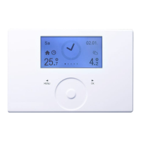
FE 7
Wedge
1 2 3 4 5 6 7 8 9 10 11 12 13 14 15 16
External
Flow
Return
DHW
2nd HS
Source
Mixer
Pulse
1
3
Bus H
Bus L
Bus –
Bus +
Sensor 1
Sensor 2
Mains N
Mains L
ESC L‘
Pumps L
Buffer 1
Buffer 2
Source
Heat 1
Heat 2
DHW
DHW Circ
2. HS
2. HS
Mixer +
Mixer –
Solar
X1 Mains voltage area
1 N
2 L
3 L‘ ESC enable signal
4 Pumps L (voltage input for relay outputs)
5-6 Buffer loading pumps
7 Source pump
8-9 Heating circuit pumps
10 DHW loading pump
11 DHW circulation pump
12-13 Second Heat source
14 Mixer OPEN
15 Mixer CLOSE
16 Solar heating pump
X2 LV area
1 Outside temperature sensor
2 Sensor HP flow temperature
3 Sensor HP return temperature
4 Sensor DHW temperature
5 Sensor second heat source
6 Sensor heat source temperature
7 Sensor mixer flow temperature
8 Heat meter pulse input
9 Terminal 1 of the FE 7 remote control
10 Terminal 3 of the FE 7 remote control
11-13 BUS high, low and ground
14 „+“ (only connected in accordance with the “DCOactiv” controller )
15 Rotary selector for heat metering
DHW cylinder bottom for solar heating connection
16 Flow sensor for heat metering
Collector sensor for solar heating connection
X3 Earth
X4 N
X5 PE

 Loading...


