17
5 Commissioning
The system can be commissioned after the
installation of all heating components required
for the proper operation and after all electri-
cal cables/leads have been connected.
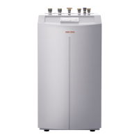
A heat pump system can comprise many dif-
ferent components. A sound knowledge of the
system function is therefore essential.
5.1 BUS initialisation
As part of the BUS cable connection, not only
the electrical interconnection for the system
communication will be created. As part of
commissioning, switching the BUS cable will
also allocate the equipment-specific address
required for controlling the heat pumps.
Only connect the BUS cable during
commissioning.
Observe the following sequence when making
the BUS connections:
– Connect the mains supply to the indivi-
dual heat pumps
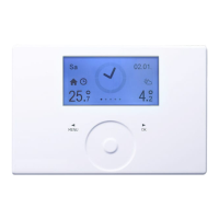
– Connect the mains supply to the WPM II
– Connect the mains supply to the MSM
(if installed)
– Set the system to standby mode to
prevent the heat pump from running
without control during initialisation
– Call up parameter 50 „Analysis“ from
system parameter „Start up“. Every
figure shown (1 to 7) represents a con-
nected heat pump.
At this point, the display must not show any
figures.
– If an MSM is installed, this must be con-
nected to the WPM II as rst device via
the BUS cable.
No more than 2 min. after the con-
nection was made, the WPM II display
must show the gure 7. Communica-
tion between both devices has been
established.
– Connect the BUS cable to the individual
heat pumps, one after the other. Any
heat pump supplied with voltage will be
allocated an address, as soon as the BUS
cable is connected. This enables WPM II
to control the heat pump.
– Check the BUS communication via para-
meter 50 „Analysis“.
After each BUS connection is made, a further
concurrent figure must be shown in the
Display after no more than 2 min. Finally the
number shown in the display must be identical
to the number of heat pumps.
After initialisation has been concluded, the
parameter „Diagnostic“ enables you to check,
whether the WPM II has found all connected
heat pumps. The display may show, for examp-
le „HP 1 found“.
Heat pump modules
The control panel for each heat pump pro-
vides space for the connection of two three-
core BUS cables, i.e. the BUS cable between
the heat pumps is wired in parallel.
Required order of the heat pumps to be
installed:
heat pumps provided for DHW loading/he-
ating must always be initialised first. All other
heat pumps can then be connected in any
order.
All necessary sensors must be
connected before the supply is
connected to the WPM II. Any sensors
connected later will not be recognised by
the WPM II.
Example: The system parameter DHW temp.
and DHW prog. will be skipped if, at the initial
start-up, the DHW cylinder sensor was not
connected. Values for these parameters can
therefore not be programmed.
All IWS must be reset in case of incorrect
initialisation,
in other words, they must be re-initialised (see
section 5.4.1).
The entire heat pump system will
be shut down, if the BUS cable
between WPM II and the heat pump is
interrupted.
5.2 System conguration through set-
tings in the commissioning report.
The commissioning report contains all settings
for the WPM II function. In case the system
operates incorrectly, initially check the settings
in the commissioning list.
5.3 Reset options WPM II
5.3.1 Reset by turning the rotary switch
from Auto to Reset and back again. All sys-
tem-specific programs remain intact. The error
list will not be deleted.
5.3.2 Reset by turning the rotary switch
from Auto to Reset and back again while
holding down the PRG key. EEPR must be
shown in the display. (EEPROM hardware
reset). The WPM II is reset into the as deli-
vered condition. The error list will be deleted.
5.4 Reset options IWS
5.4.1 IWS re-initialising
For this, proceed as follows:
– Switch OFF the mains supply to the
WPM II
– Switch OFF the mains supply to the
MSM (if installed)
– Switch OFF the mains supply to the heat
pumps
– Open die heat pumps
– Disconnect all BUS connections
– Switch ON the power supply to the
heat pump
– Press the reset button. Hold down the
button until the three LEDs light up per-
manently. Release the reset button. The
IWS is only reset at this point and ready
for a new initialisation. – Switch ON the
mains supply again
– BUS initialisation in accordance with sec-
tion 5.1
– Setting all system-specific parameters
in accordance with the commissioning
report of MSM, WPM II
Carry out this reset, if error were made du-
ring the commissioning, i.e. during the system
initialisation.
5.4.2 The IWS is reset by activating the para-
meter „Reset HP“.
The heat pump is ready for operation again.
Implement this reset if a heat pump-specific or
hardware fault has occurred five times within
5 hours.

 Loading...


