9BT 360
English
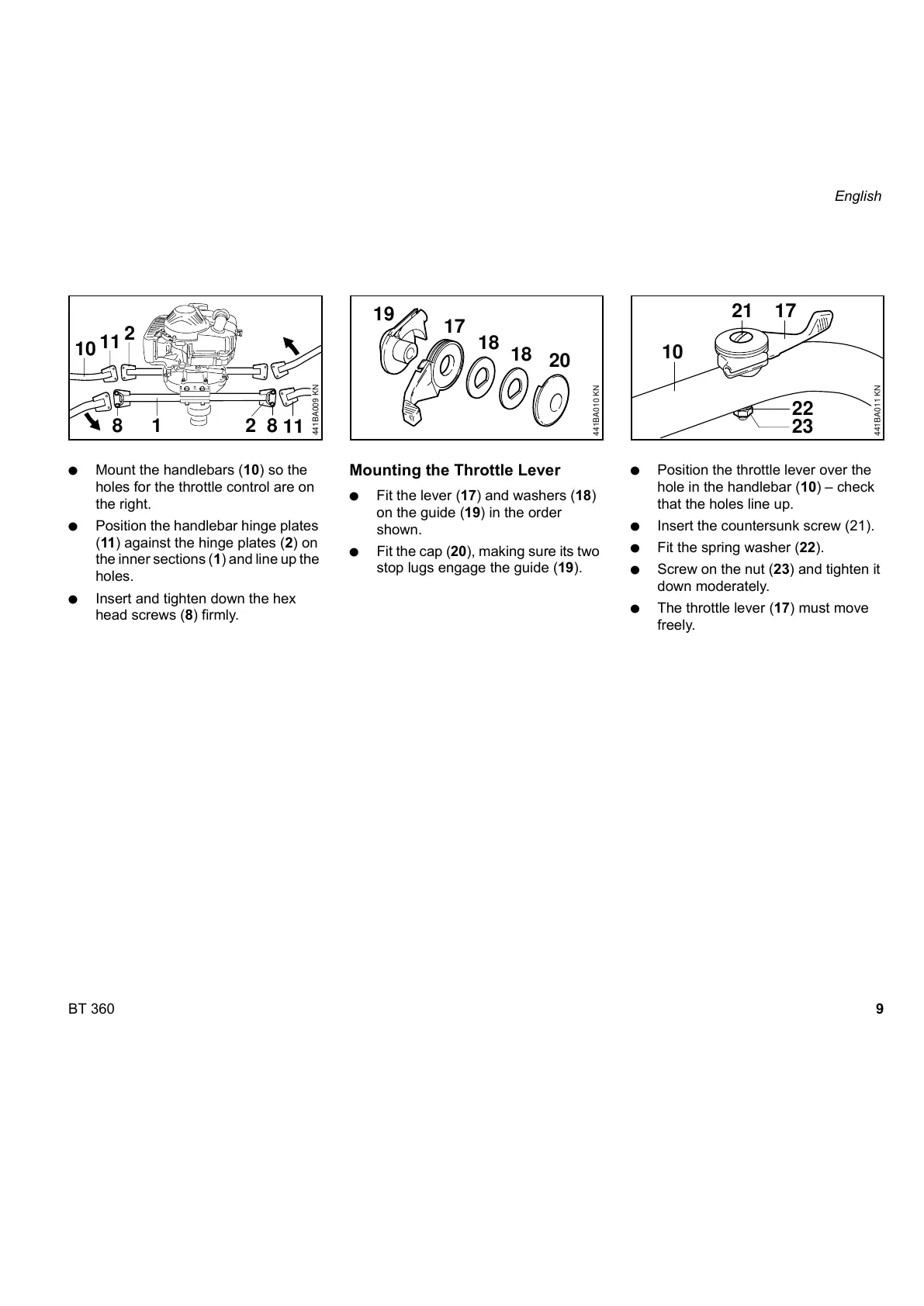
: Mount the handlebars (10) so the
holes for the throttle control are on
the right.
: Position the handlebar hinge plates
(11) against the hinge plates (2) on
the inner sections (1) and line up the
holes.
: Insert and tighten down the hex
head screws (8) firmly.
Mounting the Throttle Lever
: Fit the lever (17) and washers (18)
on the guide (19) in the order
shown.
: Fit the cap (20), making sure its two
stop lugs engage the guide (19).
: Position the throttle lever over the
hole in the handlebar (10) – check
that the holes line up.
: Insert the countersunk screw (21).
: Fit the spring washer (22).
: Screw on the nut (23) and tighten it
down moderately.
: The throttle lever (17) must move
freely.
11
441BA009 KN
12
8
10
11
2
8
441BA010 KN
17
18
19
20
18
441BA011 KN
10
17
21
22
23
 Loading...