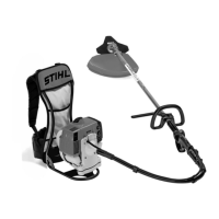
► If the trimmer or the deflector require servic‐
ing or repairs: Contact your STIHL servicing
dealer for assistance.
►
Maintain the cutting attachment as descri‐
bed in the User Manual supplied with the
cutting attachment being used or on the
cutting attachment’s packaging.
■
The user can be cut by the sharp cutting
edges while cleaning or maintaining cutting
attachments. This may result in injury to the
user.
► Wear work gloves made from resist‐
ant material.
5 Preparing Trimmer for
Operation
5.1 Preparing the Brushcutter for
Operation
The following steps must be performed before
commencing work:
► Ensure that the following components are in
safe condition:
–
Brushcutter, 4.6.1.
–
Deflector, 4.6.2.
–
Mowing head or metal cutting attachment,
4.6.3 or 4.6.4.
►
Clean the brushcutter,
15.1.
►
Mount the powerhead, 6.1
►
Mount the shaft, 6.2.
►
Mount the loop handle, 6.3.
► Select combination of cutting attachment and
deflector, 20.1.
►
Mount the deflector, 6.5.1.
► If you are using a universal deflector together
with a mowing head: Fit the skirt and line limit‐
ing blade, 6.6.1.
► If you are using a metal cutting attachment:
Mount loop handle with barrier bar,
6.4.
► Mount mowing head or metal cutting attach‐
ment, 6.7.1 or 6.8.1.
►
Fill the brushcutter with fuel, 8.2.
►
Fit and adjust the carrying system, 7.1.
►
Check the controls, 10.1.
► If you cannot carry out this work: Do not use
your brushcutter and contact your STIHL
dealer for assistance.
6 Assembling the Trimmer
6.1 Mounting the Powerhead
► Shut off the engine.
► Remove the screw (1) and washer (2).
► Hold the powerhead against the carrying sys‐
tem (3) in such a way that the flexible drive
tube (4) points to the front.
► Insert the screw (1) together with the washer
(2) and tighten it to a torque of 10 Nm.
The powerhead need not be removed again.
6.2 Fitting the Shaft
► Shut off the engine.
► Remove the screw (1).
► Remove the protective cap (2).
► Press the coupling sleeve (3) against the shaft
(4) and turn until the coupling sleeve (3) can
be pushed onto the shaft (4).
► Push the coupling sleeve (1) onto the drive
tube (3) as far as stop.
► Insert and firmly tighten the screw (1).
► Using the throttle cable retainer (6) secure the
throttle cable (4) to the flexible shaft (5) in
such a way that the throttle cable (4) is not
wrapped around the flexible shaft (5).
6.3 Mounting the Loop Handle
► Shut off the engine.
5 Preparing Trimmer for Operation English
0458-840-0101-A 11

 Loading...