► Place the clamp shells (3 and 4) on the shaft
and insert the wing screw (1).
► Pivot the handlebar (2) up and align it so that
distance (A) is about 16 cm.
In doing so, do not clamp the curved part of
the handlebar (2).
► Tighten the wing screw (1) and close the
clamp.
► Remove the screw (6).
► Position the control handle (8) on the handle‐
bar (2), trigger facing the gear housing, and
line up the hole in the control handle with the
hole in the handlebar.
When doing so, do not twist the operating han‐
dle (8).
► Fit the nut (7).
► Insert and tighten down the screw (6) firmly.
It is not necessary to remove the bike handle
again.
6.2 Removing the Deflector and
the Limit Stop
6.2.1 Installing the Deflector and the Limit
Stop
► Shut off the engine.
► Position the deflector (1) on the gear housing.
► Insert the screws (2) and tighten them
securely.
6.2.2 Removing the Deflector and Limit Stop
► Shut off the engine.
► Take out screws.
► Remove deflector.
6.3 Removing and Installing Metal
Cutting Attachment
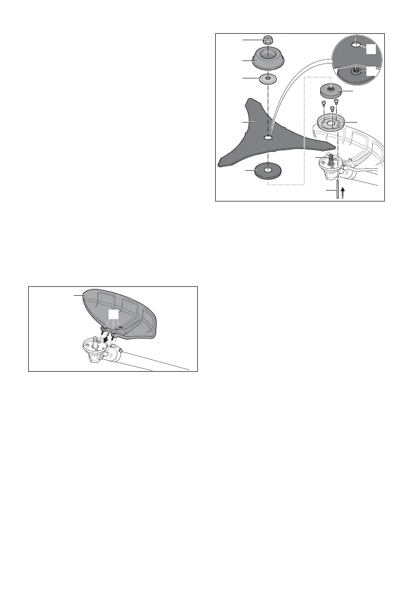
6.3.1 Mounting Brush Knives
► Shut off the engine.
9
8
6
a
b
7
5
1
2
3
4
0000099821_001
► Attach the guard ring (7) for mowing applica‐
tions.
► Fit the thrust plate (6) and guard washer (5).
► Place the brush knife (4) on the guard
washer (5).
The collar (a) must protrude into the hole (b) of
the brush knife (4).
► Place the thrust washer (3) on the brush
knife (4) so that its convex side is facing up.
► Place the rider plate (2) for the mowing attach‐
ment on the thrust washer (3) so that its
closed side faces up.
► Insert the stop pin (9) in the hole up to the limit
stop and hold it depressed.
► Turn the brush knife (4) counterclockwise until
the stop pin (9) engages in position.
The shaft (8) is now blocked.
► Fit the nut (1) counterclockwise and tighten it
down firmly.
► Remove the stop pin (9).
6.3.2 Mounting the Circular Saw Blade
► Shut off the engine.
6 Assembling the Trimmer English
0458-839-0101-A 11
 Loading...