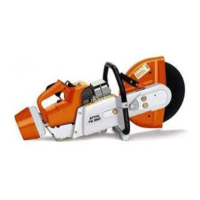
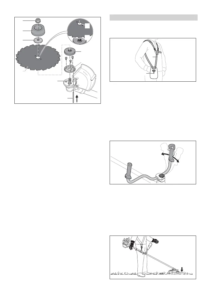
► Attach the guard ring (6) for sawing applica‐
tions.
► Fit the thrust plate (5).
► Place the circular saw blade (4) on the thrust
plate (5). Align the cutting edges so that they
face in the same direction as the arrow for the
direction of rotation on the limit stop.
The collar (a) must engage the hole (b) of the
metal cutting attachment.
► Place the thrust washer (3) on the circular saw
blade (4) so that its convex side faces up.
► Place the rider plate (2) for sawing applica‐
tions on the thrust washer (3) so that its closed
side faces up.
► Insert the stop pin (8) in the hole up to the limit
stop and hold it depressed.
► Turn the circular saw blade (4) counterclock‐
wise until the stop pin (8) engages in position.
The shaft (7) is now blocked.
► Fit the nut (1) counterclockwise and tighten it
down firmly.
► Remove the stop pin (8).
6.3.3 Removing the metal cutting attach‐
ment
► Shut off the engine.
► Insert the stop pin in the bore up to the limit
stop and hold it depressed.
► Rotate the metal cutting attachment clockwise
until the stop pin engages in position.
The shaft is now blocked.
► Unscrew the mounting nut clockwise.
► Remove the fastening parts, metal cutting tool
and pressure plate.
► Remove the stop pin.
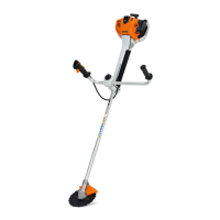
7 Adjusting Trimmer for User
7.1 Fitting and Adjusting the Full
Harness
► Putting on the Full harness (1).
► Adjust the full harness (1) so that the carabi‐
ner (2) is about a hand’s width below your
right hip.
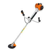
7.2 Adjusting the Bike Handle
The bike handle can be set to different positions
to suit the height and reach of the user.
► Shut off the engine.
► Hook the brushcutter from the carrying strip
into the carabiner of the carrying system.
► Loosen the wing screw (1).
► Swing the bike handle (2) to the required posi‐
tion.
► Tighten down the wing screw (1) firmly.
7.3 Balancing the Brushcutter
The brushcutter is balanced differently depend‐
ing on the cutting attachment used.
If a brush knife is fitted:
English 7 Adjusting Trimmer for User
12 0458-839-0101-A
 Loading...