Page 26 Technical Information 40.2010
TI_40_2010_13_01_02.fm
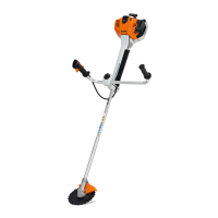
. Unscrew bolts (1)
. Remove blue lead (2) and red lead (3)
. Move choke lever to position }
. Connect M-Tronic test lead 5910 840 0903 to
the diagnostic jack, see b 9.4
Connect M-Tronic test lead to Multimeter:
. Insert black plug in "com" / "ground" jack
. Insert red plug in "volt" / "ohm" jack
. Set multimeter to "diode test"
Test diode on micro switch – follow the direction
in the multimeter Instruction Manual:
If the micro switch (switching device) is intact,
readings will match the following target values:
– Choke lever in position Start } – measurement
in direction of flow
Target value: 0.3 volts to 0.7 volts (direction of
flow)
– Choke lever in position F – reverse-biased
measurement
Target value: 1.2 volts to infinity – observe
display, e.g., display [O.L.] or [1.] (reverse bias)
If target values are not attained, check wiring
harness, see b 9.7.
Replace micro switch (switch gear) if necessary.
9.7 Checking the wiring harness
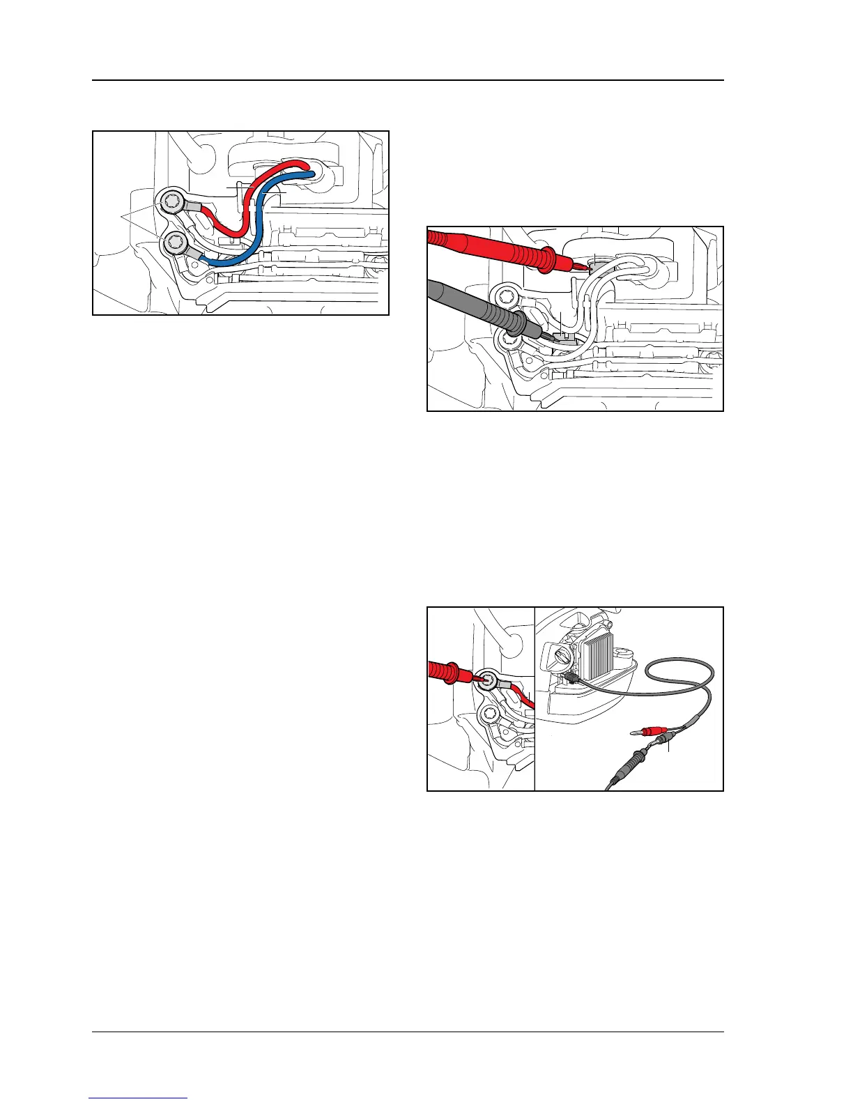
9.7.1 Checking the ground connection
. Move choke lever to position F
. Measure the resistance between lug (1) and
screw (2) at the control unit.
Target value: < 10 ohms
9.7.2 Checking leads between control unit and
diagnostic jack
. Move choke lever to position F
. Connect M-Tronic test lead 5910 840 0903 to
the diagnostic jack, see b 9.4
. Measure the resistance between red lead (1)
and black plug (2) of the diagnostic cable.
Target value: < 10 ohms
2
3
5903TI014 KN
1
2
5903TI015 KN
1
2
1
5903TI016 KN

 Loading...