135MS 261, MS 261 C
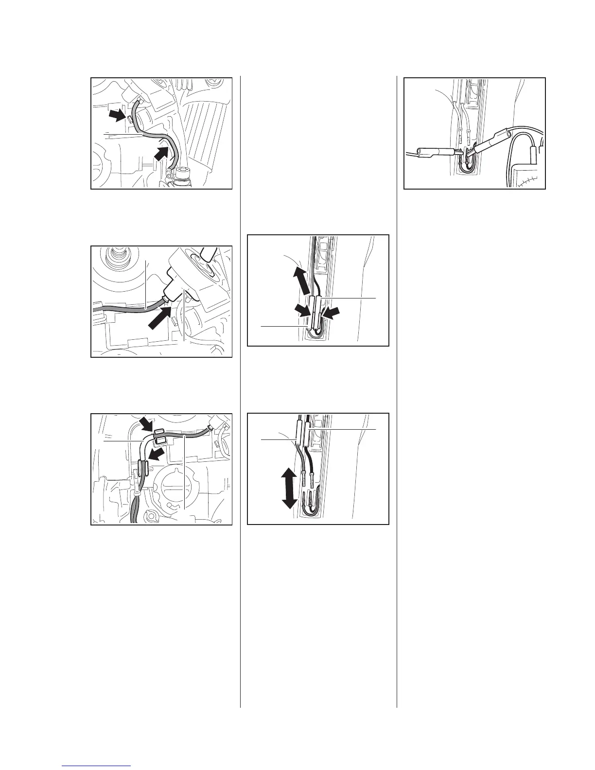
: Push the ground wire (1) into the
guides (arrows).
: Push the connector (1) into the
heater switch (2) as far as stop.
The carburetor carrier is not shown
in the illustration.
The wire (1) must be seated in the
guides so that the protective
tube (2) butts against the
guides (arrows).
– Reassemble all other parts in the
reverse sequence.
5902RA539 TG
1
5902RA540 TG
1
2
5902RA571 TG
2
1
13.5 Heating Element
in Rear Handle
The ambient temperature during
removal and installation should not
be less than + 15°C.
– Remove the handle molding,
b
10.2
: Pull the insulating tubes (1) with
connectors out of the
guides (arrows).
: Push back the insulating
tubes (1) in the direction of the
wiring harness and separate the
pin and socket connectors.
5902RA592 TG
1
1
5902RA593 TG
1
1
: Check the heating element and
replace if necessary.
If the heating element is in good
condition the ohmmeter will indicate
a value of about 2 Ω in measuring
range "Ω".
If the reading is outside this range,
install a new heating element.
Heating element does not operate
even though resistance
measurement is ok?
– Test the generator and heater
switch, b