42 MS 261, MS 261 C
: Remove the clamping strap (1)
and wooden assembly block (2).
Make sure the cylinder gasket is
properly seated.
– Push the cylinder fully home.
: Insert the screws (arrows) to hold
the cylinder and gasket in
position..
– Tighten down the screws through
the holes (arrows) in the cylinder
in a crosswise pattern.
– Reassemble all other parts in the
reverse sequence.
5902RA126 TG
1
2
5902RA116 TG
6.6 Crankshaft
– Drain the fuel and oil tanks,
b
1.1
– Remove the brake band,
5.2
– Remove the oil pump,
11.3
– Remove the oil suction hose,
11.2
– Remove the brake lever,
5.4
– Remove the handlebar,
9.6
Machines with heating,
9.6.1
– Remove the tank housing,
12.11.5
– Remove the flywheel,
7.6
– Machines with handle heating
Remove the generator,
13.7
– Remove the short circuit wire,
7.7.2
– Remove the cylinder,
6.7
– Remove the spiked bumper.
– Remove the insulating mat,
6.1
Always install new bearings and oil
seals after removing the crankshaft,
6.3.
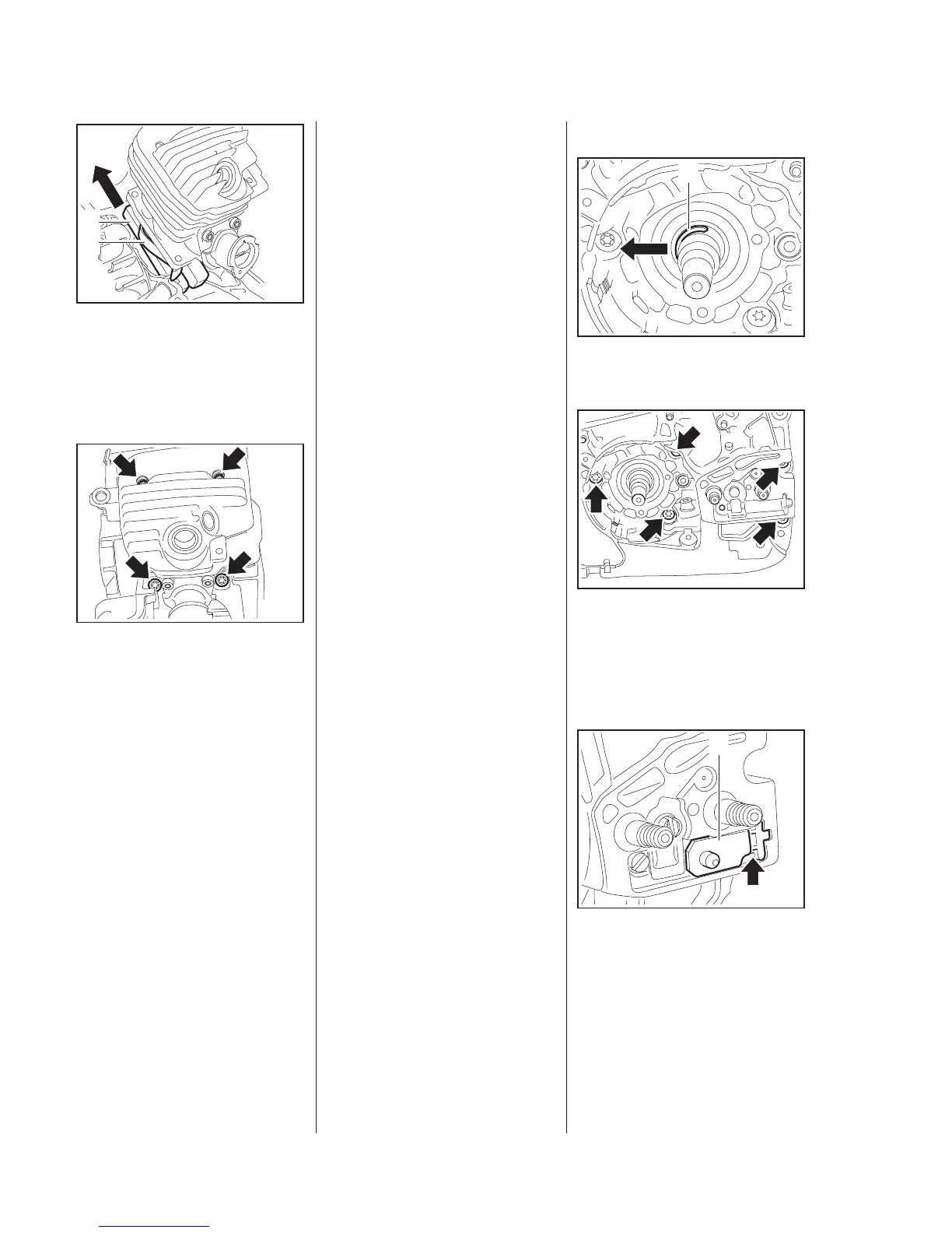
Clutch side of crankcase
: Remove the retaining ring (1).
Use the tools in the service tool set
5910 007 2205 for removing and
installing.
: Take out the screws (arrows).
: The tensioner slide (1) must butt
against the thrust pad (arrow).
5902RA103 TG
1
5902RA128 TG5902RA129 TG
1