59MS 311, MS 391
9.5 Stop Buffer at Clutch
Side
The stop buffers are located
between the tank housing and
engine housing. They are fitted at
the ignition and clutch sides.
– Remove the tank housing,
b 12.11.4
– Remove the cover, b 5.2
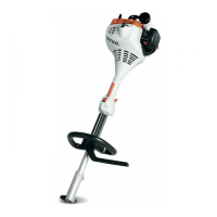
: Ease the stop buffer (1) out of the
bore.
Installing
– Position the stop buffer (1)
with its short end facing the
engine housing.
– Use STIHL press fluid to simplify
assembly, b 14
4903RA150 TG
1
4903RA149 TG
1
: Push the stop buffer (1) into the
bore and make sure it is properly
seated.
– Reassemble all other parts in the
reverse sequence.
9.6 Annular Buffer at Ignition
Side
– Remove the ignition module,
b 7.3
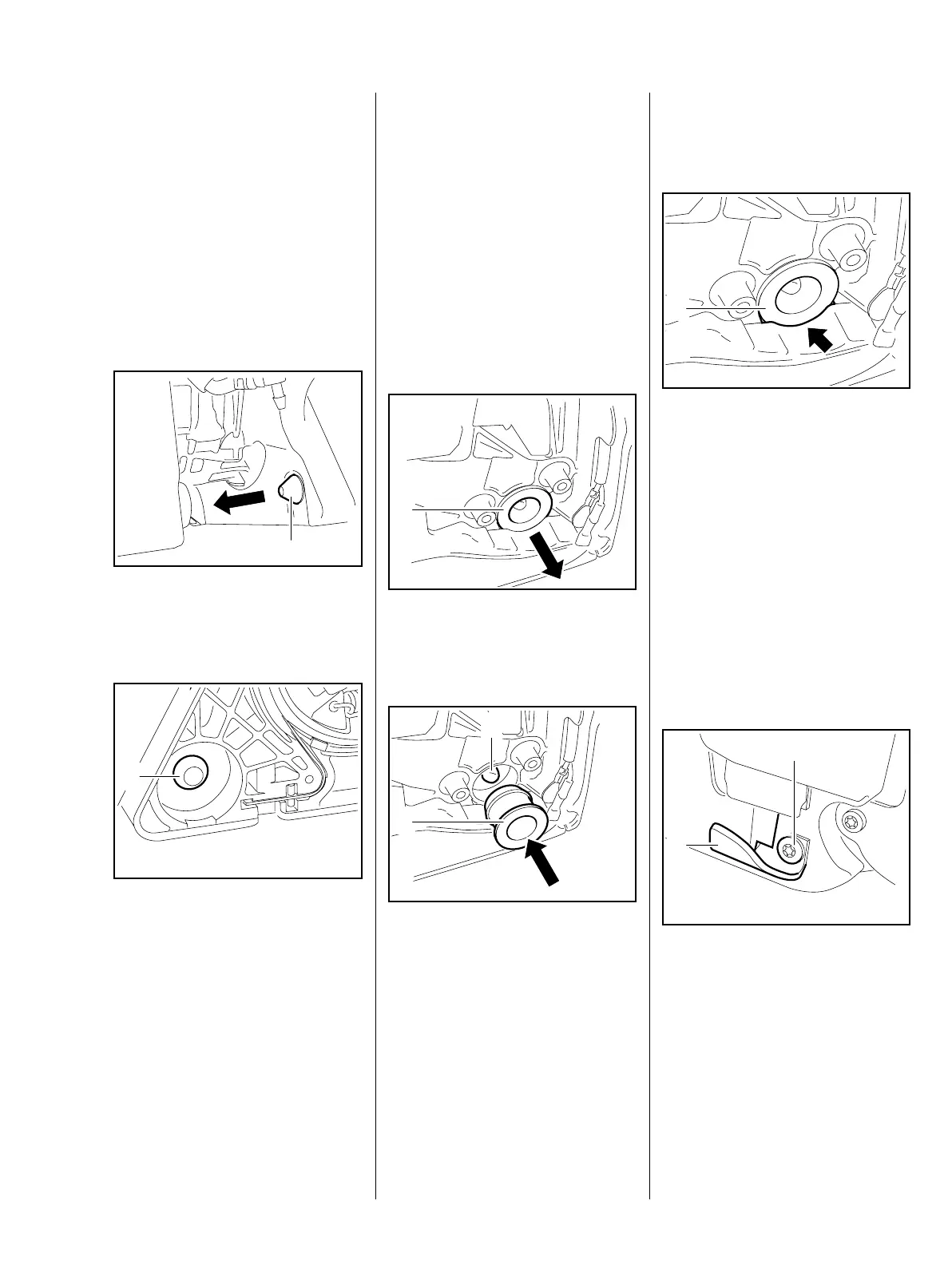
: Pry out the annular buffer (1).
Installing
– Line up the annular buffer (1)
with its tapered end facing the
engine housing.
– Use STIHL press fluid to simplify
assembly, b 14
4903RA151 TG
1
4903RA152 TG
1
2
: Push home the annular buffer (1)
so that its bore engages the peg
(2) in the tank housing.
: Annular buffer (1) must be
properly seated in the
recess (arrow).
– Reassemble all other parts in the
reverse sequence.
9.7 Handlebar
– Remove the shroud, b 6.4
– Remove AV spring from
handlebar, b 9.4
: Take out the screw (1) and
remove the chain catcher (2).
4903RA148 TG
1
4903RA153 TG
2
1

 Loading...