61MS 311, MS 391
10. Control Levers
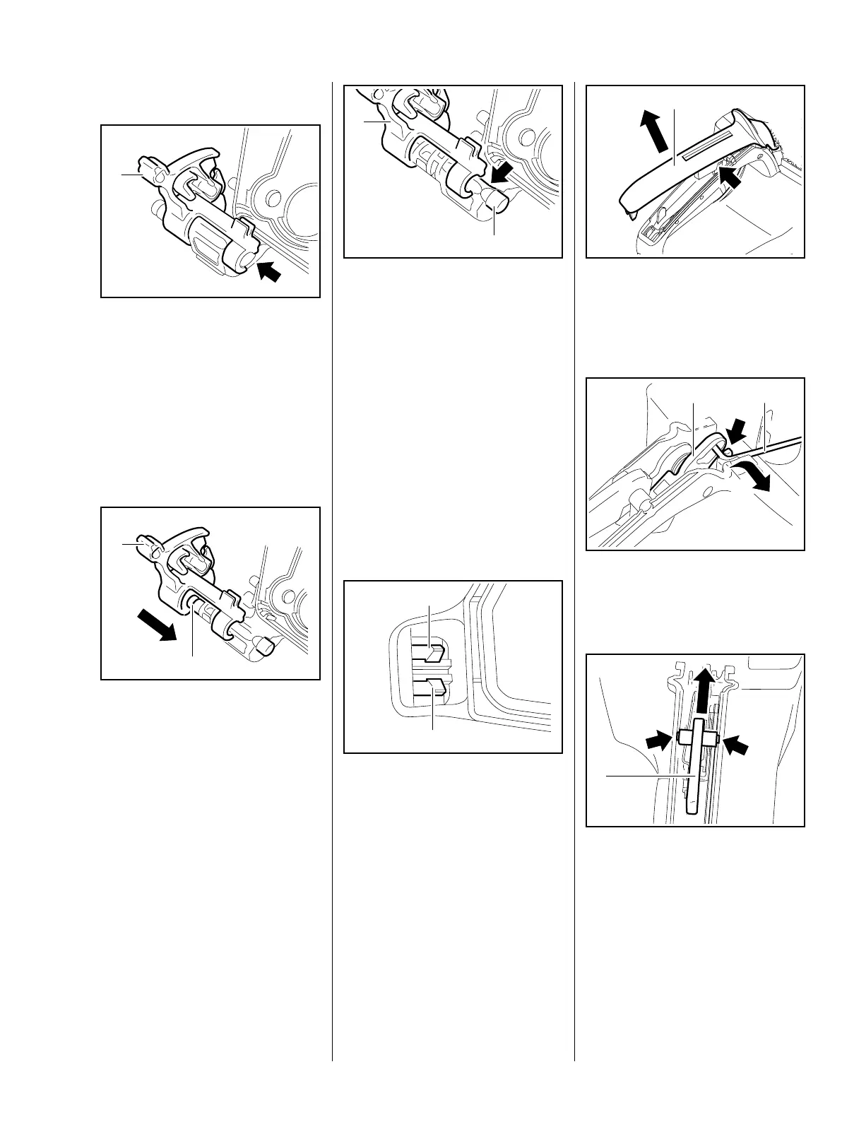
10.1 Master Control Lever
– Remove the filter base, b 12.3
: Pry the switch shaft (1) out of its
mount (arrow).
: Lift the switch shaft (1) a little and
pull it away.
Installing
: Push the switch shaft (1) onto the
pin (2).
4903RA157 TG
1
4903RA158 TG
1
2
: Carefully push the switch shaft
(1) over the taper (arrow).
: Push the switch shaft (1) onto the
pin (2) until it snaps into position.
– Install the filter base, b 12.3
– Reassemble all other parts in the
reverse sequence.
– Check operation.
10.2 Throttle Trigger/Interlock
Lever
: Push the tabs (1) apart and
through the tank housing.
4903RA159 TG
1
2
1
1
0001RA274 TG
: Remove the handle molding (1).
The interlock lever (arrow) may
pop out.
: Take the throttle rod (1) out of the
guide (arrow) and disconnect it
from the throttle trigger (2).
: Ease the interlock lever (1) out of
its mounts (arrows).
– Disconnect the torsion spring and
remove the interlock lever.
1
4903RA160 TG
2
0001RA276 TG
1
1
4903RA161 TG

 Loading...