41MS 650, MS 660
: At the chain tensioner side of the
crankcase, use a 4 mm drift (2) to
drive the dowel pin out of the two
halves of the crankcase.
VA
176RA106
1
2
: At the clutch side of the
crankcase, use a 4 mm drift (2) to
drive the dowel pin out of the two
halves of the crankcase.
178RA206
VA
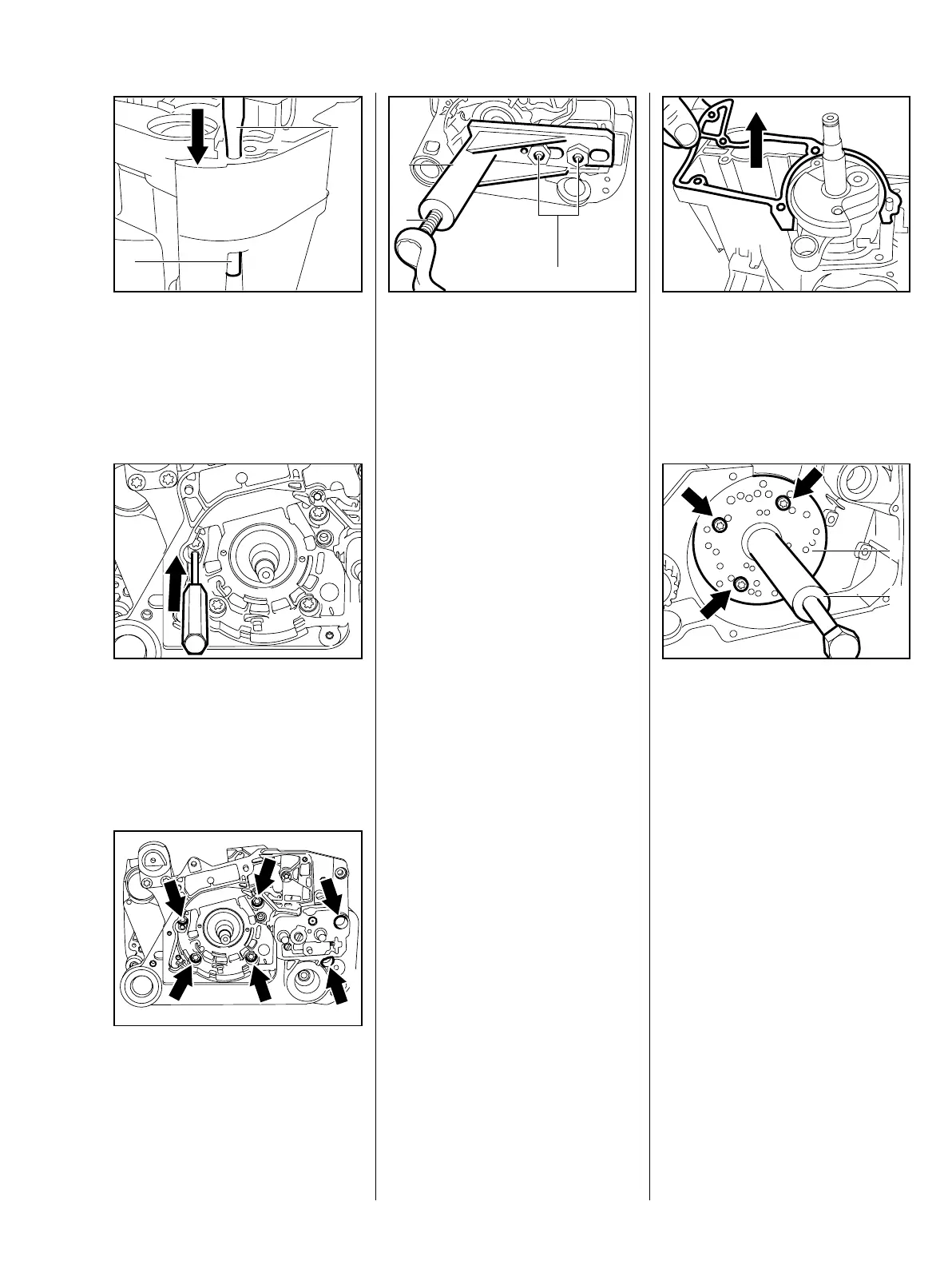
– Take the heat reflecting foil off
the crankcase.
: Remove the screws (arrows)
from the two halves of the
crankcase.
178RA205
VA
– Remove the chain tensioner –
b 5.6
: Back off the spindle (1) in service
tool AS 5910 007 2205 all the
way.
: Slip service tool AS (2) over the
VA
176RA107
2
3
1
two collar studs.
: Fit the hex nuts (3) (for sprocket
cover) and tighten them down by
hand.
: Turn the spindle (1) of the service
tool clockwise until the crankshaft
is pressed out of the ball bearing.
The two halves of the crankcase
separate during this process.
– Remove the service tool AS.
: Remove the gasket from the
crankcase.
178RA207
VA
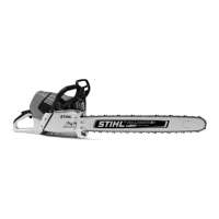
– Unscrew the spindle of service
tool ZS (1) 5910 007 2220 a little
(left-hand thread)
: Position the service tool ZS (1)
5910 893 2101 against the
flywheel side so that number 11
is at the bottom.
11
178RA208
VA
11
11
11
1
2
The cylinder flange faces up.
: Fit three M5x72 screws (arrows)
in the holes marked “11“ and
tighten them down against the
drilled plate.