42 MS 650, MS 660
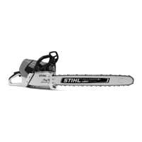
: Turn the spindle (1) counter-
clockwise until the crankshaft is
pushed out of the ball bearing.
178RA209
VA
1
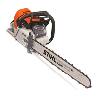
: The crankshaft (1), connecting
rod (2) and needle bearing form
an inseparable unit. It must
always be replaced as a
complete unit.
When fitting a replacement
crankshaft, always install new oil
VA
176RA111
1
2
seals and ball bearings.
: Use press arbor (1)
1122 893 7200 to press the ball
bearing at the flywheel side out of
the crankcase, from the outside
inwards
178RA210
1
VA
: Use the press arbor (1)
1124 893 7200 to press the ball
bearing at the clutch side out of
the crankcase, from the inside
outwards.
– Inspect both halves of the
crankcase for cracks and replace
178RA211
VA
1
if necessary.
The crankcase must be replaced as
a complete unit even if only one half
is damaged.
Check the condition of all other
parts, replace if necessary and
transfer to the new crankcase.
If only the ball bearings are
replaced, all rubber and polymer
components, such as oil suction
hose and annular buffers, may be
left in position.
If the crankcase has to be replaced,
all the components still fitted must
be removed and checked for
damage. This involves the following
operations:
– Remove the annular buffers –
b 9.1
– Unscrew the bar mounting studs
– b 5.7
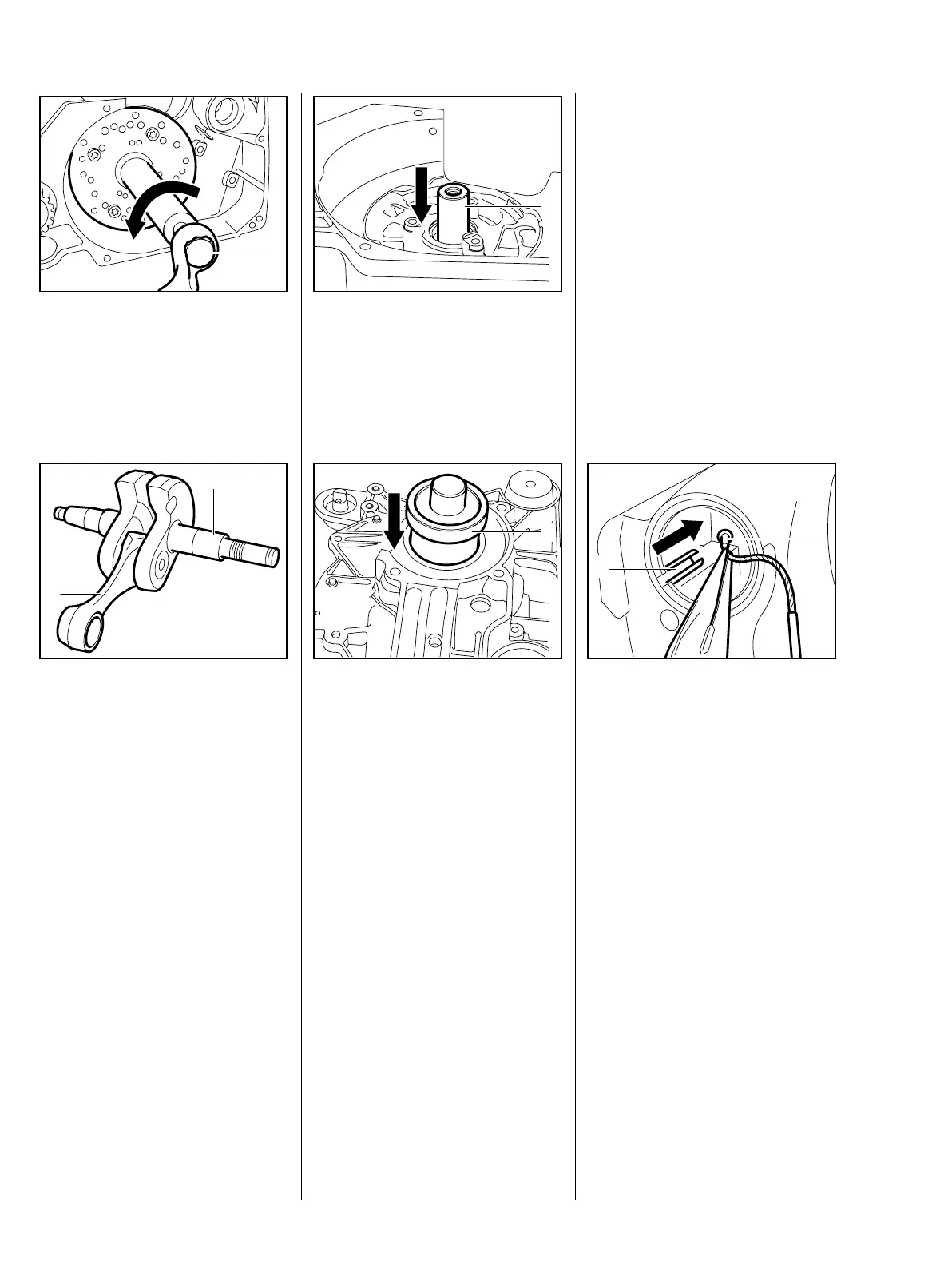
: Remove nipple of tank cap cord
(1) from the slot (2).
– Remove the tank cap.
VA
212RA196
2
1
 Loading...