132 MS 661, MS 661 C-M
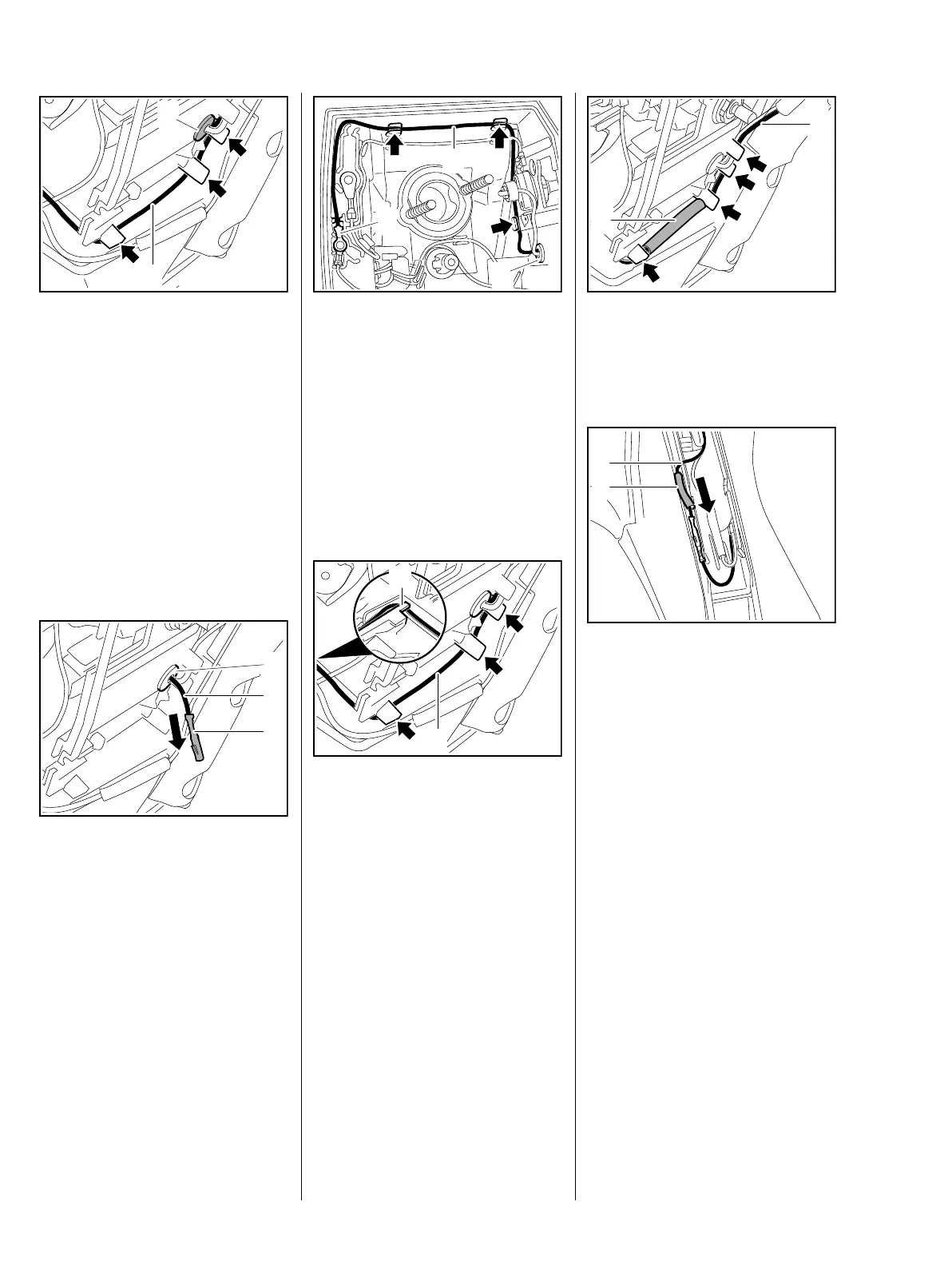
: Pull the connecting wire (1) out of
the guides (arrows) and out of the
grommet (2) in direction of
manifold.
– Check the connecting wire and
replace if necessary
– Inspect the grommet, if
necessary pull out wire on heater
switch and replace the grommet
– remove the grommet outwards.
Installing
: Push the connecting wire (1),
connector (2) first, through the
grommet (3) from inside.
1166RA405 TG
1
2
1166RA406 TG
2
1
3
: Position cable lug (1) with its
crimped side facing outwards
and route the connecting wire (2)
behind the heater switch, and
push it into the guides (arrows).
: Pull the connecting wire (2) out
through the grommet (3) in
direction of handlebar until there
are no more loops – the wire
must not be under tension.
: Push the generator connecting
wire (1) into the guides (arrows)
and then hook it tightly around
the lug (2) – connecting wire to
handlebar and must be hooked in
place and underneath the
generator wire.
1166RA407 TG
1
2
3
1166RA408 TG
1
2
: Position insulating tube (1) with
pin and socket connector on tank
housing and push wire (2) into
the guides (arrows).
: Fit the insulating tube (1) on the
generator connecting wire (2).
: Push the pin and socket together
until they lock.
: Slide the insulating tube (1) over
the pin and socket connector.
1
2
1166RA398 TG
1166RA409 TG
1
2
 Loading...