83MS 661, MS 661 C-M
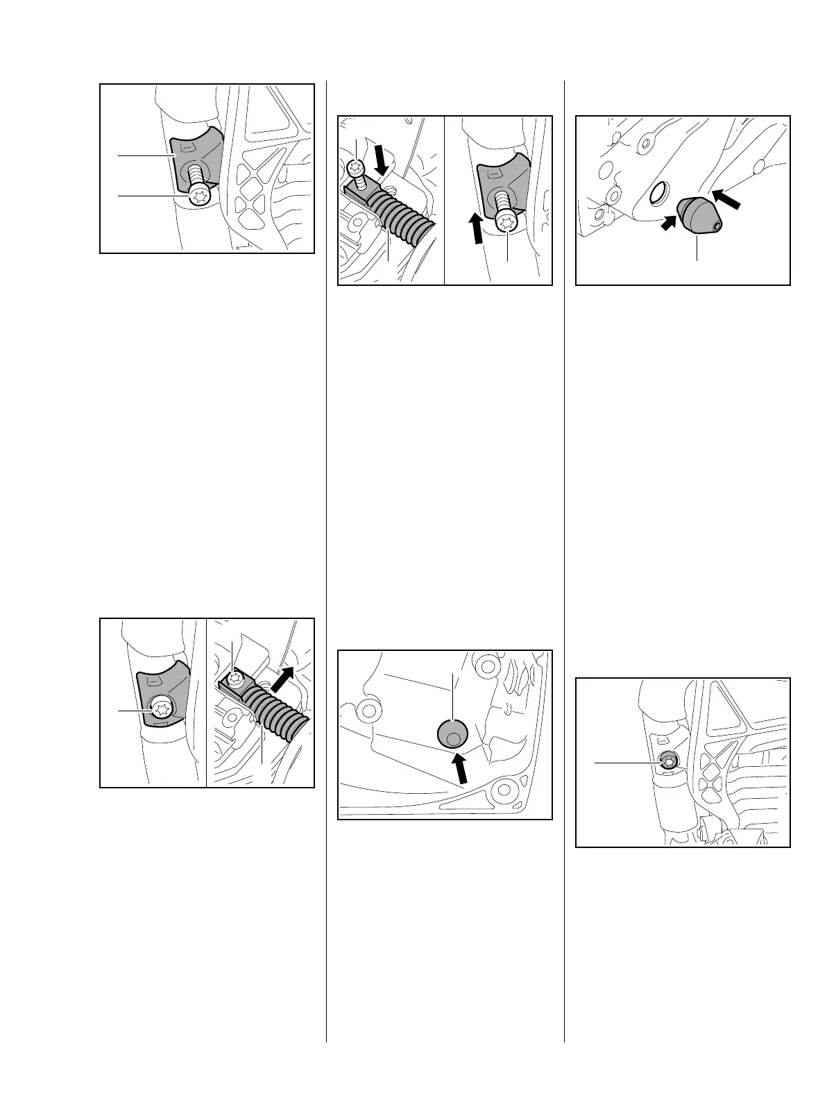
: Fit bearing plug (1) in position.
: Coat the screw (2) with
threadlocking adhesive, fit it and
tighten it down firmly, b 16
– Reassemble all other parts in the
reverse sequence.
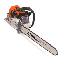
10.4 AV Element on Handlebar
The AV element is located between
the handlebar and cylinder.
– Remove the shroud, b 6.4
– Remove the air filter, b 13.1
: Take out the screws (1, 2) and
remove the AV element (3).
– Inspect the AV element and
replace if necessary.
1
2
1166RA189 TG
1
1166RA190 TG
2
3
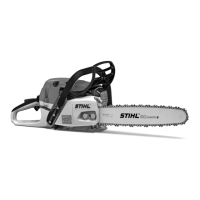
Installing
: Position the AV element (1) on
the handlebar and cylinder.
: Insert and tighten down the
screws (2, 3) firmly.
– Reassemble all other parts in the
reverse sequence.
10.4.1 Stop Buffer at
Ignition Side
– Remove the ignition module /
control unit, b 7.3
– Remove the tank housing,
b 13.11.4
: Ease the stop buffer (1) out of the
bore.
– Inspect the stop buffer and
replace if necessary.
2
1166RA191 TG
31
1166RA192 TG
1
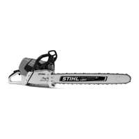
Installing
– Use STIHL press fluid to make
installation easier, b 16
: Position the stop buffer (1) with
its small tapered end (arrow)
facing the crankcase and push it
into the bore while turning it
slightly at the same time.
The tapered end must be properly
seated in the bore at the ignition
side.
– Reassemble all other parts in the
reverse sequence.
10.5 Handlebar
– Remove the shroud, b 6.4
: Take out the screw (1).
1166RA193 TG
1
1166RA180 TG
1

 Loading...