131MS 661, MS 661 C-M
: Fit the insulating tube (1) on the
generator connecting wire (2).
: Push the pin and socket together
until they lock.
: Slide the insulating tube (1) over
the pin and socket connector.
– Push the wires into the guide
between the rib and handle
heating so that the connecting
wire to the handlebar is
underneath the connecting wire
to the generator.
: Push the insulating tubes (1) with
connectors into the guides
(arrows).
– Reassemble all other parts in the
reverse sequence.
1166RA400 TG
1
2
1166RA401 TG
1
1
2
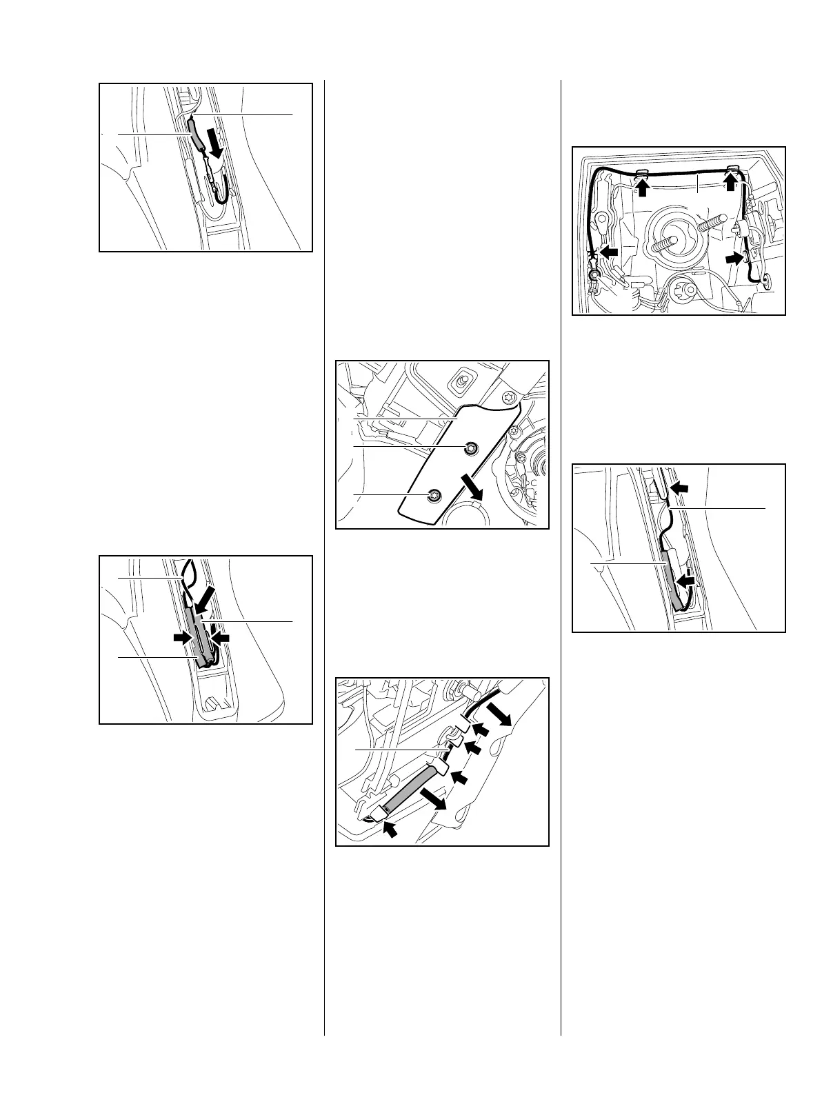
14.8.2 Connecting Wire
between Rear Handle and
Generator
– Remove the filter cover
– Remove the handle molding and
lockout lever, b 11.2
– Remove the carburetor, b 13.4
– Pull the retainer with switch shaft
out of the guide and put it to one
side, b 11.1.1
: Take out the screws (1) and
remove the cover (2).
Connecting Wire between Rear
Handle Heating Element and
Handlebar
: Pull connecting wire (1) with pi
and socket connector out of the
guides (arrows) and put it to one
side.
1
1
2
1166RA196 TG
1
1166RA402 TG
Connecting Wire between Rear
Handle Heating Element and
Generator
: Take out the screw (1), pull the
connecting wire (2) out of the
guides (arrows) – screw (1) has
already been removed on
machines with carburetor
heating.
: Pull the connecting wire (1) and
insulating tube (2) wit pin and
socket connector out of the
guides (arrows).
: Push back the insulating tube (2)
in the direction of connecting wire
and separate the pin and socket
connector.
– Pull the insulating tube off the
connecting wire.
1166RA403 TG
2
1
1166RA404 TG
1
2
 Loading...