84 MS 661, MS 661 C-M
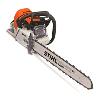
: Take out the screws (1) and
remove the cover (2).
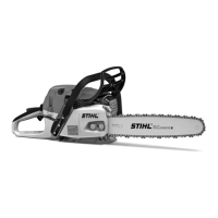
: Ease the handlebar (3) sideways
and take it out of the guide.
: Remove the screws (1) from the
underside of the machine, pry the
handlebar holder (2) out of the
handlebar (3).
: Lift the handlebar holder slightly
and pull out handlebar (3)
between handlebar holder (2)
and tank housing (4).
: Remove the handlebar (3), check
it and replace if necessary.
– Inspect handlebar holder with AV
spring and annular buffer, replace
if necessary, b 10.4
1
1166RA181 TG
1
3
2
1
3
1
1166RA194 TG
42
Installing
– Place the handlebar in position.
: Fit handlebar (1) between
handlebar holder (2) and tank
housing (3), push pegs (arrows)
into handlebar (1) and place
handlebar holder (2) in position.
– Insert the screws and tighten
them down firmly.
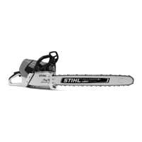
: Lift the handlebar (1) sideways
and position it in the
guide (arrow) so that the peg (2)
engages the seat in the
crankcase.
1166RA195 TG
2
3
1
2
1166RA187 TG
1
: Position cover (1) with bosses in
holes in handlebar (2), making
sure the tab (3) engages the
groove (arrow).
: Insert and tighten down the
screws (4) firmly.
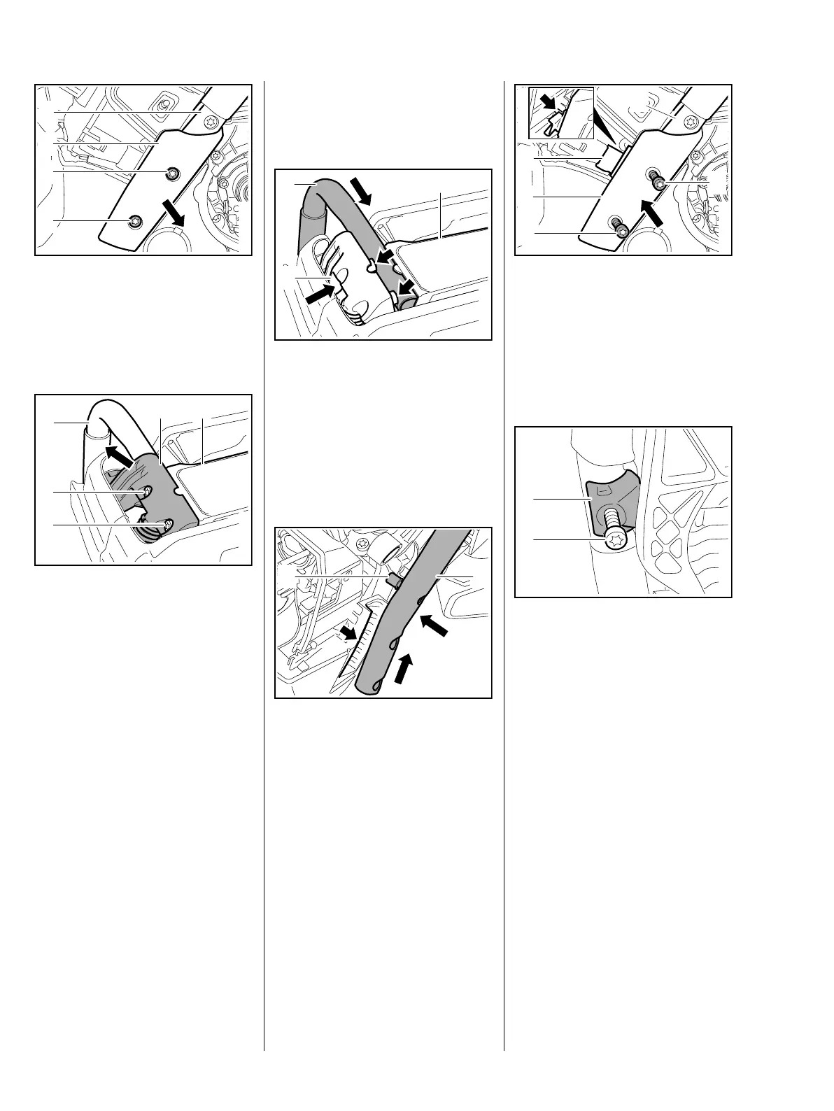
: Fit bearing plug (1) in position.
: Coat the screw (2) with
threadlocking adhesive, fit it and
tighten it down firmly, b 16
– Reassemble all other parts in the
reverse sequence.
1166RA188 TG
1
4
3
4
2
1
2
1166RA189 TG
 Loading...