53MS 661, MS 661 C-M
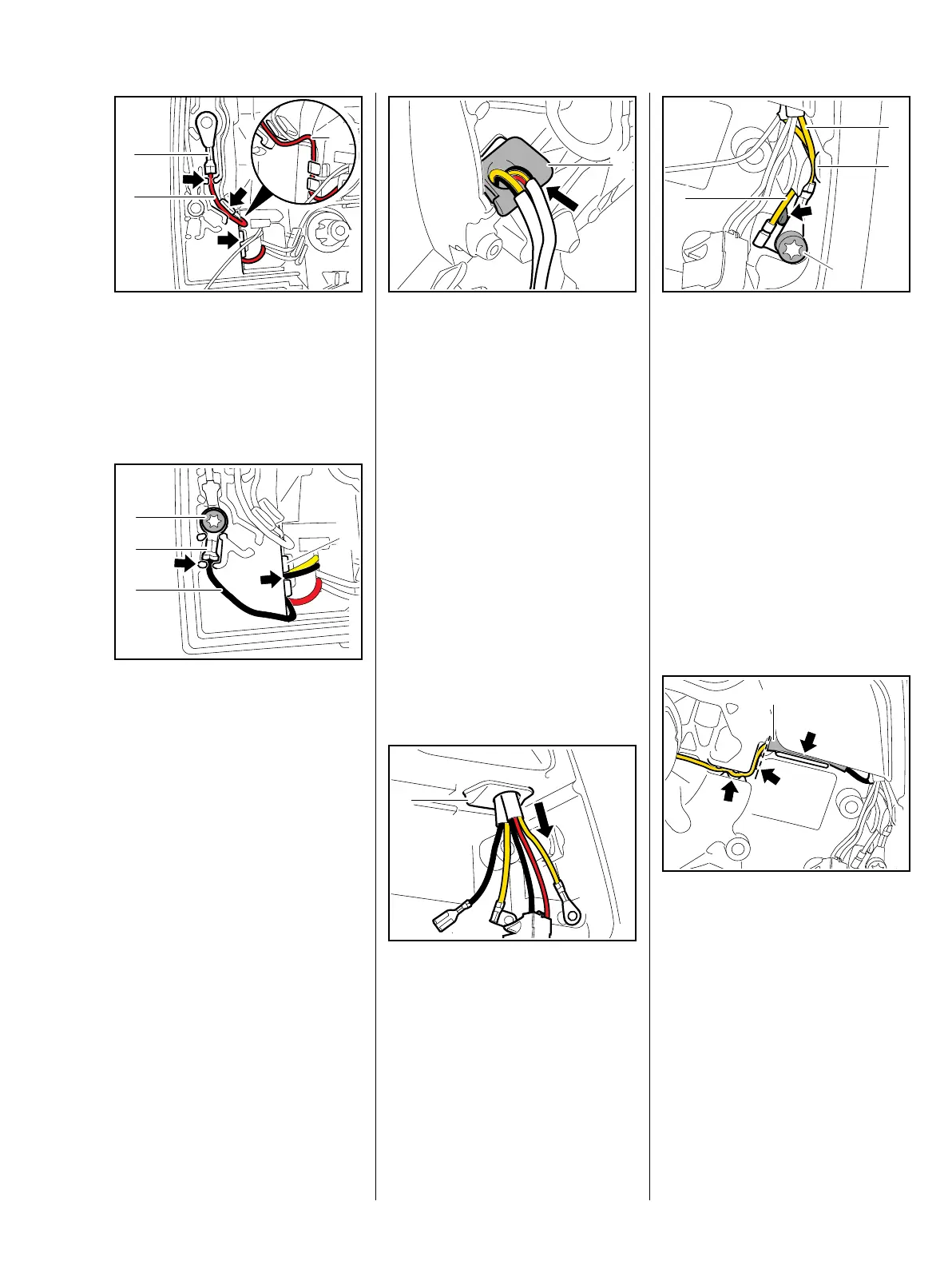
: Position cable lug (1) with its
crimped side facing outwards
and push the M-Tronic's red
wire (2) into the guides (arrows)
as shown
– loop (3) allows for movement.
At the guide (4), the yellow and red
wires must be positioned below the
black wire in that order.
: Position cable lug (1) with its
crimped side facing outwards
and push the heating's black
wire (2) into the guides (arrows).
: Insert and tighten down the
screw (3) – on machines with
carburetor heating, install the
carburetor and carburetor
heating first, then insert and
tighten down the screw (3) firmly.
3
1166RA152 TG
1
2
3
4
– Use STIHL press fluid to make
installation easier, b 16
: Fit wiring harnesses through
opening in crankcase, push
grommet (1) home sideways and
press it into the opening in the
crankcase until it is properly
seated.
– Install the tank housing,
b 13.11.4
– Install the carburetor, b 13.4
– Install the contact spring and
retainer, b 7.12
– Install the switch shaft, b 11.1.1
– check its operation, b 7.12
The grommet (1) must be properly
seated in the opening.
: Pull the wiring harnesses through
until the insulating tubes (2, 3)
project.
1166RA153 TG
1
1166RA154 TG
1
: Position cable lug of ground
wire (1) so that the crimped side
faces outwards and it butts
against the rib (arrow), then push
the ground wire (1) into the
guide (2).
: Position cable lug of ground
wire (3) so that the crimped side
faces outwards and then push
the ground wire (3) into the
guide (2).
– Ground wire (1) must be
underneath ground wire (3).
: Insert and tighten down the
screw (4) firmly.
: Reconnect the pin and socket
connector and center the
insulating tube (1) on the
connector.
: Push the pin and socket
connector with insulating tube (1)
and wire into the guides (arrows).
1166RA155 TG
2
1
4
3
1166RA156 TG
1

 Loading...