67MS 661, MS 661 C-M
Installing
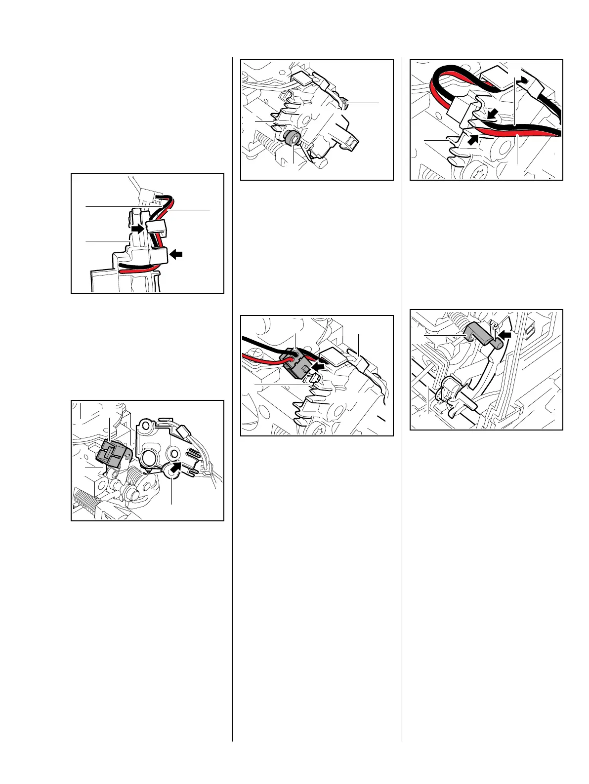
If a new switch unit is being used,
first fit the wires in the switch unit's
guides.
The wires and plug connections
must not be damaged.
: Push the red wire (1) and black
wire (2) into of the
guides (arrows) in the switch
unit (3)
– position the wires parallel to
one another as shown.
: Solenoid valve (1) must rest
against the rib (2), reposition it if
necessary and then test it,
b 8.3.4
: Position the switch unit (3) so that
the solenoid valve (1) engages
the recess (arrow).
1166RA277 TG
1
2
3
1166RA278 TG
1
2
3
: Place the solenoid valve (1) in
position.
: Coat screws (2) with
threadlocking adhesive, b 16
: Insert and tighten down the
screws (2) firmly.
: Position the connector (1) so that
guide lug (arrow) faces the
switch unit (2).
: Push connector (1) into solenoid
valve's socket (3) as far as stop.
1166RA279 TG
2
1
2
1166RA280 TG
2
1
3
: Push the red wire (1) and black
wire (2) into of the
guides (arrows) in the switch
unit (3)
– position the wires parallel to
one another as shown.
Check operation
: Move the choke shaft (1) to in
direction of cold start }, the
lever (2) must operate the
microswitch (arrow) in this
process
– with an audible click.
– Install the carburetor – all wires
must be properly seated in their
guides, b 13.4
– Reassemble all other parts in the
reverse sequence.
1166RA281 TG
2
1
3
1166RA234 TG
2
1
 Loading...