89MS 661, MS 661 C-M
: Fit the switch shaft (1) under the
throttle rod and against the
retainer (2) and lateral pivot
mount (arrow).
: Lift the contact spring (1) a little
and push pivot pin of switch
shaft (2) into the hole (arrow) in
the retainer (3), then press the
switch shaft (2) into the pivot
mount (4) so that it snaps into
position.
Models without M-Tronic
: Short circuit wire (1) must be
seated in the guide (2) – loop
(arrow) allows for movement.
1166RA297 TG
1
2
1166RA298 TG
2
1
3
4
1166RA299 TG
1
2
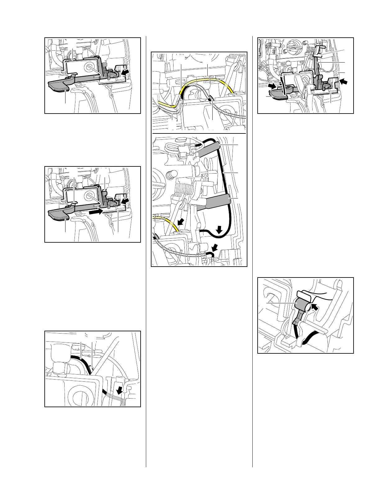
Models with M-Tronic
: Ground wire (1), short circuit
wire (2) and M-Tronic wire (3)
must be seated in the guides (4,
5, 6), push them into the guides if
necessary – loops (arrows) allow
for movement.
1 4
2 5
6
6
3
1166RA440 TG
: Move the switch shaft (1) in
direction of "STOP" and hold it
there. Push the retainer (2) into
the guides in the tank housing (3)
until the locking tabs (arrows)
engage, position lever (4) behind
lever (5) on choke shaft at the
same time.
– Install the throttle trigger, b 11.2
All models
– Attach throttle rod to throttle
trigger and install handle
molding, b 11.3.1
Check operation
: Short circuit wire's ring
terminal (1) must touch the
contact spring (arrow) in position
"0".
– Reassemble all other parts in the
reverse sequence.
1166RA170 TG
1
2
3
4
5
1166RA223 TG
1

 Loading...