0458-828-9621-B
29
English
3 Overview
2 Locking lever
The locking lever holds the battery in the battery
compartment.
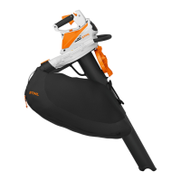
3 Loop handle
For holding and controlling the vacuum shredder.
4 Shield
The shield protects the user from moving parts inside the
vacuum shredder.
5 Suction tube
The suction tube guides the sweepings into the vacuum
shredder.
6 Nozzle
The nozzle guides the sweepings to the suction tube.
7 Catcher bag
The catcher bag collects the sweepings.
8 Shoulder strap
Serves to carry the vacuum shredder.
9 Retaining latch
The retaining latch retains the control handle in its
position.
10 Control handle
The control handle is used to operate, control and carry
the vacuum shredder.
11 Ergo lever
The Ergo lever holds the release slide in position when
the trigger is released.
12 Release slide
The release slide releases the trigger.
13 Trigger
Switches the vacuum shredder on and off.
14 Blower tube
The blower tube directs the air stream.
15 Nozzle
The nozzle directs and controls the air stream.
16 Battery
The battery supplies the blower with energy.
17 LEDs
The LEDs indicate the state of charge of the battery and
any faults.
18 Button
The button activates the LEDs on the battery.
# Rating plate with machine number
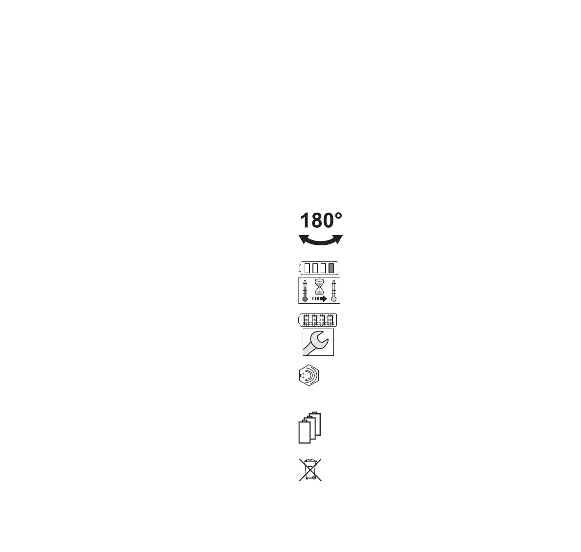
3.2 Icons
Meaning of icons that may be on the vacuum shredder and
the battery:
This symbols indicates that the control handle
can be rotated 180°.
1 LED lights up red. The battery is too warm or
too cold.
4 LEDs flashing red. There is a fault in the
battery.
Guaranteed sound power level in accordance
with Directive 2000/14/EC in dB(A) for the
purpose of comparing the sound emissions of
products.
The information next to the symbol indicates the
energy content of the battery according to the cell
manufacturer’s specification. The energy content
available in operation is lower.
Do not dispose of the product with domestic waste.
L
W
 Loading...