SN6000 model
For more information on Ethernet interfaces, please refer to the section Connecting to the network in the
chapter INSTALLATION PRECAUTIONS.
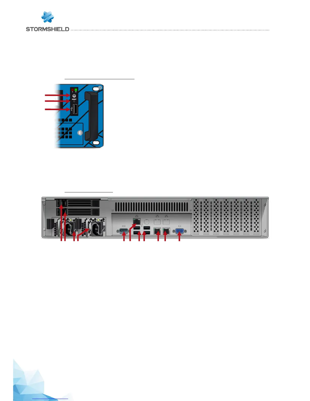
Front panel: connectors and LEDs
1. The Power button allows switching the Firewall on or off.
2. The Reset button: electrically resets the Firewall.
3. The USB 2.0 port can be used for secure configurations or upgrades. You can also connect a
USB key, a USB keyboard or an approved USB modem.
Rear panel: connectors
1. SSD racks for log storage (2 in RAID 1). The LEDs on SSD racks confirm whether the SSD has
been accessed (bottom blue LED) and installed (top green LED).
2. Two mains sockets for redundant power supplies.
3. The serial port allows accessing the product in console mode; it is possible to connect the
Firewall directly from a computer. The default baud rate on this model is 9600 baud (8N1).
4. A network port dedicated to the administration of the appliance via IPMI. Please refer to the
appendix for information on the configuration and administration via IPMI.
5. Four USB 2.0 ports that can be used for secure configurations or upgrades. You may also
plug in a USB key, USB keyboard or approved USB modem.
6. Two network ports dedicated to the management of the appliance or a High Availability
configuration (from left to right: MGMT1 and MGMT2).
7. The VGA port allows connecting a monitor.