Pull sealing
tape back
Remove the plug
New
thumbwheel
Remove insert
The text in brackets refers to the corresponding user guide
chapter. [Chapter Number]
TIP COMPATIBILITY [3]
IDENTIFYING TIPS [3]
PLATEN VACUUM [3]
Make sure the vacuum gauge reads -15Hg or higher (more
negative) before building or calibrating. See Troubleshooting:
Low Vacuum if gauge is out of range.
USING BUILD SHEETS [4]
Use clear build sheet for ABS-M30, PC, and PC-ABS.
Use amber build sheet for PPSF and ULTEM.
Use green tinted build sheet for Nylon 12.
INSTALLING CANISTERS [4]
Remove the anti-rotation plug from side of
canister before use. Seal hole with sealing tape.
Make sure the rubber shipping insert is removed
from the thumbwheel door before building.
Do not remove rubber shipping insert until
the canister is loaded into the canister bay.
Storing Canisters
Always replace the rubber shipping insert
when storing a partially used canister. Store
canister vertically (as if it is installed in a
system) or cross-winding of the lament on
the inner spool may result.
CHANGING TIPS OR MATERIAL TYPE [4]
1. Remove the used build sheet from platen.
2. Clean the oven and tip wipe assembly.
3. Inspect the tip wipe assembly.
4. From the Main Menu select; Operator Control > Change
Tips/Mtl.. > Unload Model and Support. Wait until the
material unloads before continuing to the next step.
107161-0012_REV_A
5. If changing material type:
- Remove the canisters. If removing a partially used canister,
you must remove it immediately (within ten seconds) after
separating drive block from canister; otherwise the lament is
forced into the canister, making it unusable.
- Seal the canisters and store vertically.
- Insert new canisters and turn the thumbwheel to put the
canister in the “Ready” state (ashing LED).
Note: If material type is changed, the tips MUST be changed.
Do not use the same tip for dierent material types.
6. Change the liqueer tips.
- If the removed tips are to be
re-used later, record material
type and volume.
- Make sure that you insert the
tip fully into the heater block.
Note: Worn tips cause part quality issues and can lead to loss of
extrusion. Always replace tips when prompted (reset
tip odometers).
7. From the menu, choose Select Materials/Tips..
8. If changing material type:
- Select Review Materials to Load.. and choose materials to load.
- Select Menu to continue.
9. Choose Select Tips to toggle through tip choices.
The system automatically does the following:
- Waits for oven to stabilize
- Performs Auto Z Zero calibration
- Loads model and support material
- Performs Auto Tip-to-Tip calibration
- Builds Calibration Job
MATERIAL DRYING SYSTEM [4]
Call Customer Support if the air pressure does not read between
36-40 psi for internal air or 48-52 psi for external air.
AUTO COOL-DOWN FEATURE [4]
This option acts as an energy saver when PC, PC-ABS, ULTEM, or
PPSF materials are being used. It also helps to prevent parts from
cracking when building large, thick parts using PPSF. After building
completes, the oven gradually cools to the standby temperature.
Wait until the PPSF parts are cool before removing them from the oven.
ULTEM
9085
STABILIZING OVEN [4]
When changing material type or using Auto Cool-Down, allow oven
temperatures to stabilize before calibration and system use. Oven
stabilization times are as follows:
10. Select Reset Tip Odometers.. and enter the odometer values for
the new tips.
11. If user placement is on, choose Select Calibration Part Position
and make user placement selections.
12. Select Load and Calibrate..
13. Select Unlock Door and insert a new build sheet. If switching to or
from PPSF, wait for the oven to stabilize before inserting a new
build sheet.
14. Determine Calibration Job tip oset values. See Calibration Job
for more information.
Make sure
tip is fully
inserted into
block
ABSi
Oven Stabilization Times (in hours)
ABS-
M30
ABS-
ESD7
Nylon
12
PC-
ABS
PC/
PC-ISO
ABS-M30
Auto
Cooldown
Nylon 12
ASA
ABSi
Room temp.
ABS-ESD7
PC-ABS
PC/ PC-ISO
ULTEM 9085
ULTEM 1010
ASA
4 4 4 4 4 4 4 8 8 8
--- --- --- --- --- 4 4 6 6 6
--- --- --- --- --- 4 4 6 6 6
--- --- --- --- --- 4 4 6 6 6
--- --- --- --- --- 4 4 6 6 6
4 4 4 4 4 ---
4 6 6
4 4 4 4 4 4 ---
4 4 4
6 6 6 6 6 4 4 ---
6 6 6 6 6 4 4 ---
PPSF
6
4
PPSF
6 6 6 6 6 6 4 4 ---
ULTEM
1010
Table 1-3: Oven Stabilization Times
---
4
4
---
Table 1-1: Available Tips
Table 1-2: Slice Height
Material Model Tip Support Tip
ABSi
ABS-M30
ABS-M30i †
ABS-ESD7 †
Nylon 12
PC
PC-ABS
PC
PC-ISO †
PC
PC-ISO †
PPSF †
ULTEM 9085 †
T10, T12, T16, T20
T10, T12, T16, T20
T12, T16
T12, T16, T20
T10, T12, T16
T10, T12, T16, T20
T16, T20
T12
T16
T16, T20
T12SR20
T12SR20 /
T12SR30
T12SR30
T12SR-100
T12SR-100
T12SR20
T16
T12
T16
T16
ASA
T10, T12, T16, T20
T12SR30
ULTEM 1010 † T14, T20
T16
† 400mc only
Model Tip Slice Height
T12
T16
T20
0.007 in. (0.178 mm)
0.010 in. (0.254 mm)
0.013 in. (0.330 mm)
T14
0.010 in. (0.254 mm)
T10
0.005 in. (0.127 mm)
All unused model and support
tips are interchangeable -
EXCEPT for Soluble
Release (SR) support tips.
Once a tip is used, it is
committed to that material
type and is no longer
interchangeable.
Tip size is imprinted on
the top side of the plate
(T10 T12, T14, T16, T20)
The Soluble Release
support tip is shorter
than standard tips.
Tip size is imprinted on
the top side of the plate
(T12SR20, T12SR30,
T12SR100).
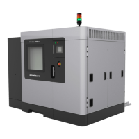
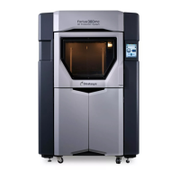
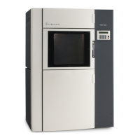
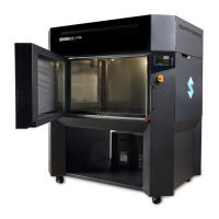
QUICK REFERENCE CARD
Fortus 360mc/400mc and FDM 360mc/400mc