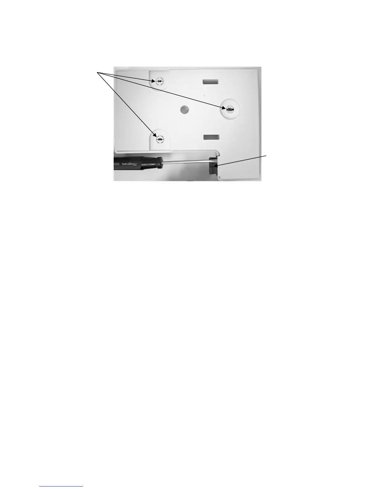
C. Compress the mounting posts and remove the base plate of the charging rack.
Mounting Posts
Key Slot
D. The power input connector has a key slot that faces toward the base plate of the rack.
1. Testing the standard power input connector. (See pictures on Page 26.)
a. Place the charge rack with the charge contacts down and the power input
connector to the right.
b. Place a multimeter into the continuity mode.
c. Place one meter lead into the right-hand (positive) contact of the power input
connector.
d. Place the other meter lead onto the solder pad where the positive (red) lead is
connected to the charge rack PC Board.
e. The meter should indicate continuity.
f. Follow the same procedure using the negative contact of the power input
connector and the solder pad where the negative(black) lead is connected to
the charge rack PC Board.
g. If the meter does not indicate continuity, and no obvious repairable problems are
evident (broken solder joints, etc…), the PCB assembly will need to be replaced.
The power input cord is not available separately.
- 25 -