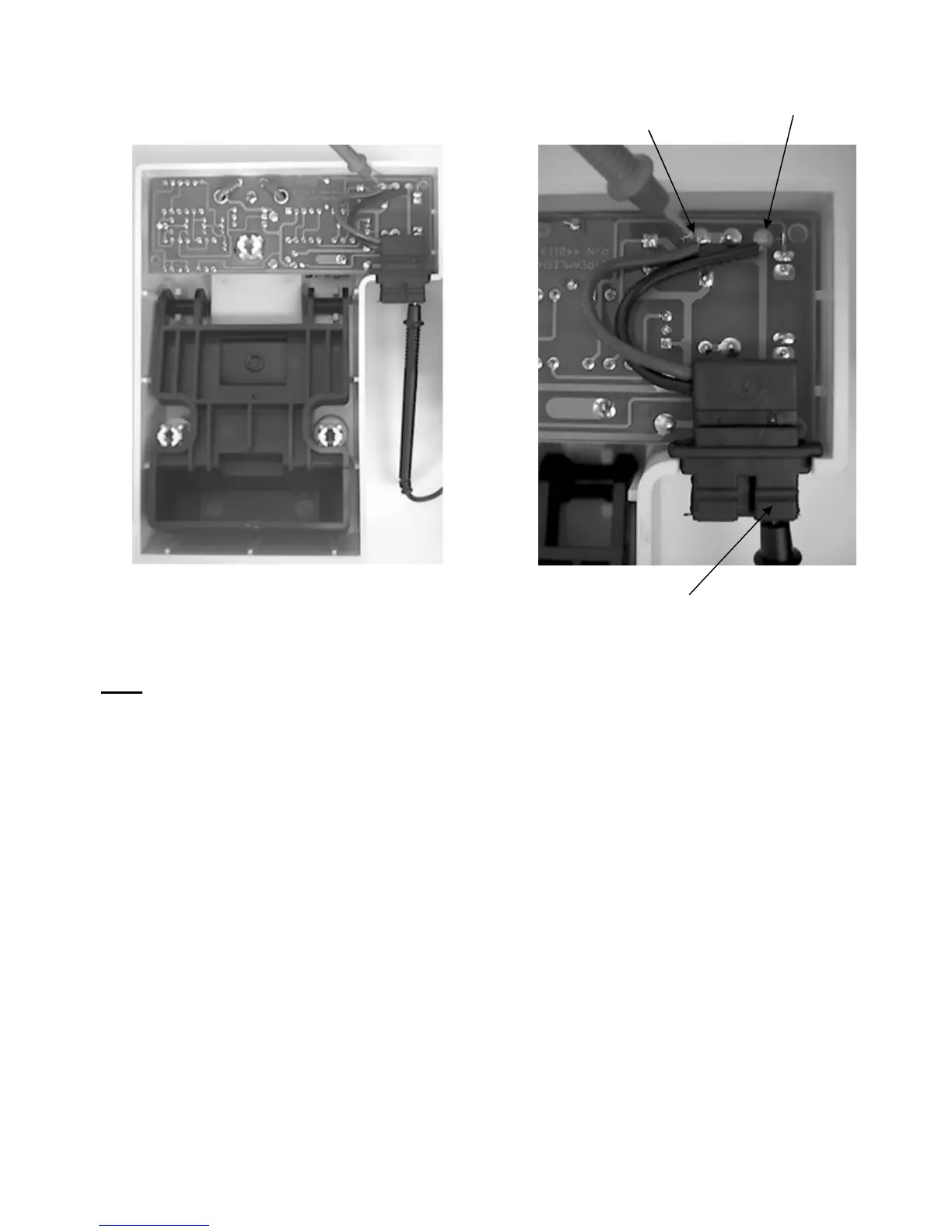
Positive contact
PC Board
Positive contact
Power In
ut
Negative contact
2. Testing the Direct Wire power input leads.
Note: Disconnect charge racks with permanently wired input power from the input source.
a. Disassemble the charge rack as directed on page 24, Testing the Internal Wiring.
b. Place a multimeter into the continuity position.
c. Place one meter lead on the positive power input lead (red stripe).
d. Place the other meter lead onto the solder pad where the positive power lead is
connected to the Printed Circuit Board.
e. The meter should indicate continuity.
f. Follow the same procedure using the negative lead and the other solder pad.
g. If the meter does not indicate continuity, and no obvious repairable problems are
evident (broken solder joints, etc…), the PCB assembly will need to be replaced.
The power input cord is not available separately.
- 26 -