Height sensors Height sensors
Selecting the sensor position
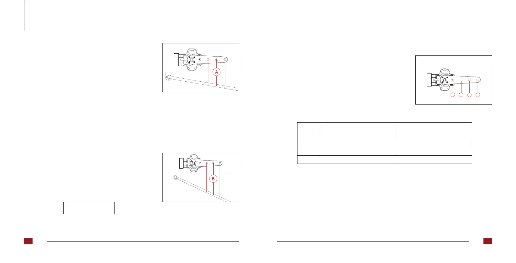
1. Attach the sensor to the vehicle and place the sensor arm
in the center position. Disconnect the air line from the air
bellows and raise the suspension to the lower end stop of
the chassis using a gear jack. Measure the distance [A]
from the sensor arm to the selected attachment point of
the coupling rod (Fig. 23). Make sure that the attachment
points are suitable for the entire travel distance of the
trolley/vehicle.
2. Reconnect the air line and apply enough air pressure
to the air bellows until the landing gear is at the upper
end stop. Now measure the distance [B] from the sensor
arm to the selected attachment point of the coupling rod
again (Fig. 24). The difference between the two measured
values gives the maximum travel [C].
Abb. 23: Coupling rod attachment point
Abb. 24: Coupling rod attachment point
Selecting the correct mounting hole for the coupling rod in the sensor arm.
1 2
3 4
Abb. 25: Sensor arm mounting holes
Hole
1
2
min. path C [mm]
18
30
4
80
3
52
max. path C [mm]
30
52
120
80
The maximum angle for the height sensor is 120 degrees.
Selecting the correct mounting hole ensures that this value
is not exceeded. The selection of the correct mounting hole
(Fig. 25) is made using this table.
C = B - A
30 31
 Loading...