55 mm
D
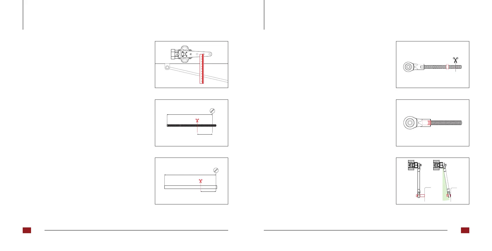
Abb. 28: Sensor arm middle position
Abb. 30: Screwing in the threaded rod
Abb. 31: Coupling rod angle
Abb. 29: Marking the intersection
Adjusting the length of the coupling rod
1. Using a gear jack, move the suspension to the center
position of the entire travel range and the sensor arm to
the center position of the working range. Now measure the
distance [D] between the selected mounting hole and the
mounting point of the coupling rod (Fig. 26).
Abb. 26: Sensor arm length
40 mm
D
Abb. 27: : Shortening the threaded rod
2. Shorten the threaded rod of the coupling rod. The length
of the threaded rod must be 40 mm less than the distance
measured in point 1 (Fig. 27).
3. Shorten the rubber cover on the threaded rod. The length
of the rubber cover must be 55 mm less than the distance
[D] measured in point 1 (Fig. 28).
4. If you do not have a tap available for deburring the
threaded rod, screw a nut onto the threaded rod before
cutting the rod. Use the nut to deburr the end of the rod
(Fig. 29)..
5. Screw the threaded rod into both heads of the couplingrod
about ten turns deep. This gives you an adjustmentrange
of about +/- 10 mm in length for any correctionsthat may
be necessary later. (Fig. 30)
6. Mount the coupling rod on the sensor arm and on
theattachment point on the suspension. Pay attention to
theangle between the coupling rod and the sensor arm
(Fig.31). This may be a maximum of 15 degrees and can
be corrected using spacers at the attachment point.
Height sensors Height sensors
32 33



 To Next Page