Page 14 of 38
3.2.6 USB VME Master Status/Control register (read/write)
#define SIS3153USB_VME_MASTER_CONTROL_STATUS 0x10
The control register is in charge of the control of most of the basic properties of the SIS3153
board in write access. It is implemented via a selective J/K register, a specific function is
enabled by writing a 1 into the set/enable bit, the function is disabled by writing a 1 into the
clear/disable bit (which location is 16-bit higher in the register). An undefined toggle status
will result from setting both the enable and disable bits for a specific function at the same
time.
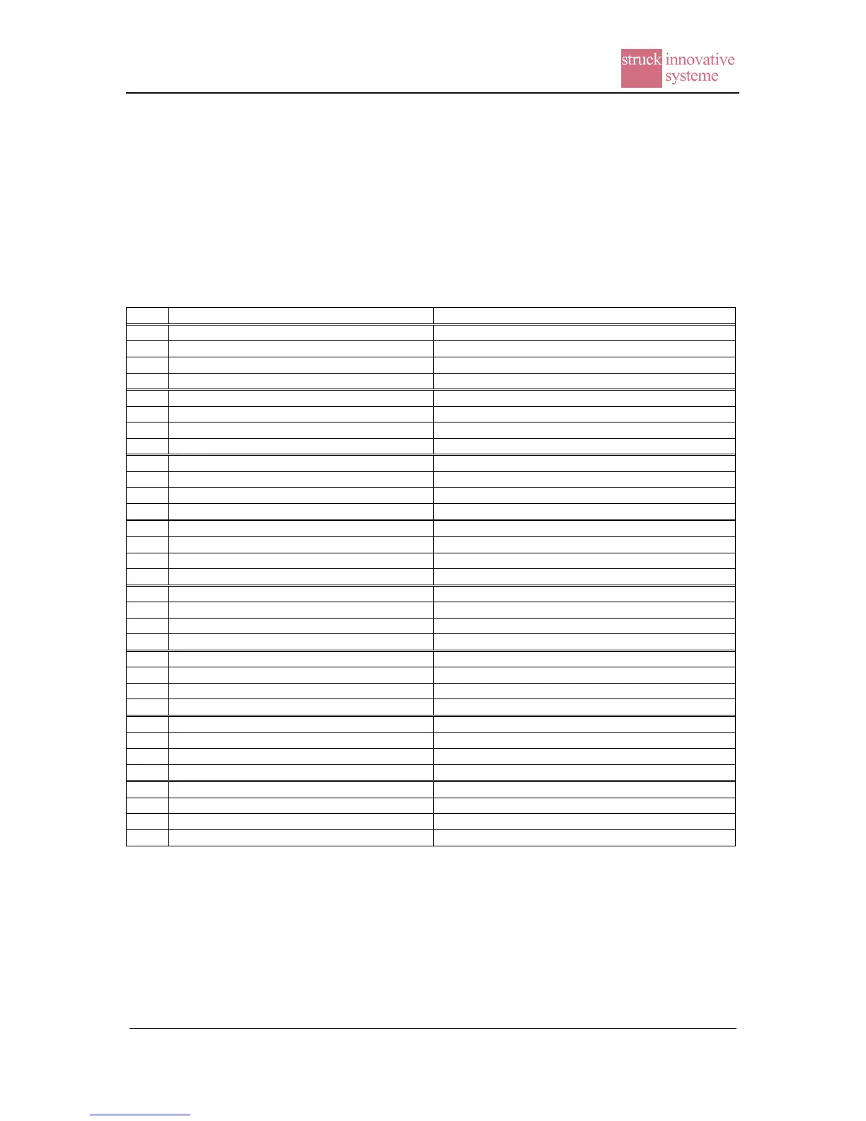
Clear SYSTEM VME BERR TIMER BIT1
Clear SYSTEM VME BERR TIMER BIT0
Clear VME REQUESTER TYPE BIT
Clear VME System Controller Enable bit
Status VME System Controller (*2)
Set SYSTEM VME BERR TIMER BIT1
Status SYSTEM VME BERR TIMER BIT1
Set SYSTEM VME BERR TIMER BIT0
Status SYSTEM VME BERR TIMER BIT0
Status Force Dearbit Enable bit
Status VME retry Enable bit
Set VME REQUESTER TYPE BIT
Status VME REQUESTER TYPE BIT
Status VME_REQ_LEVEL BIT1
Status VME_REQ_LEVEL BIT0
Set VME_SYSRESET bit (*3)
Set VME System Controller Enable bit (*1)
Status VME System Controller Enable bit
The power up value is 0x0000C100 (or 0x0001C100 with system controller set)
Notes:
(*1) is ored with switch 5 of SW162; Caution: if the jumper is not installed and the VME
system controller functionality is enabled by software, the 16 MHz clock is not active
during power up. This may result in problems with peculiar VME slave designs that use
the VME clock to initialise on board logic.
(*2) is set with switch 5 of SW162 on or if VME System Controller Enable bit is set