Setting Up the 1088 Camera
13
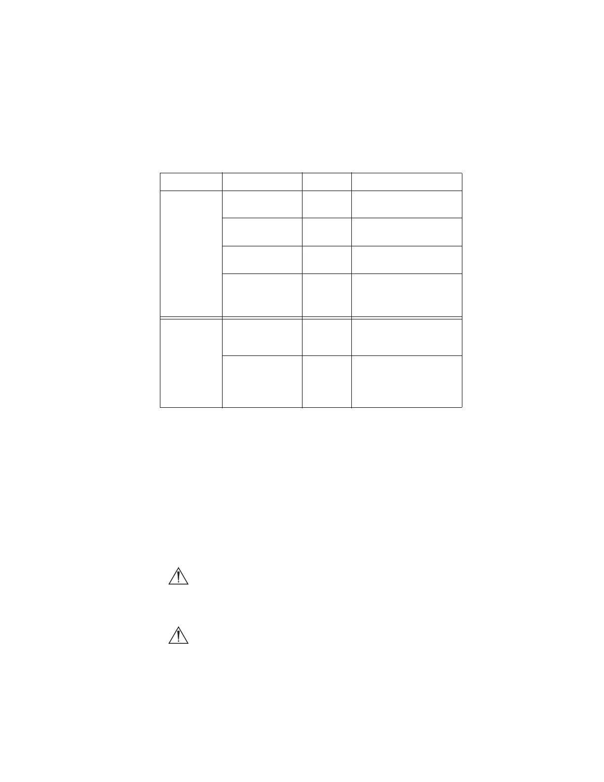
2. Connect the video output.
• The rear panel provides four analog and two digital-video
outputs, which can be used together or independently:
• Use the cables and outputs described above to connect the
1088 to other operating-room equipment. Diagrams 1-3 on the
following pages describe typical set-ups.
• If desired, connect any remote outputs using the remote cables
supplied with the 1088 Camera. (See Diagram 2.) Devices
connected to the remote outputs of the 1088 Camera can be
operated by using the buttons on the camera head. See the
“Operating the Camera Head” section of this manual for details.
• If desired, connect the Sidne™ interface as well. (See Diagram
2.)
Warning When the 1088 Camera is used with other equipment,
leakage currents may be additive. Ensure that all
systems are installed according to the requirements of
IEC 60601-1-1.
Warning Do not touch the internal pin of the VIDEO-OUT BNC
jack and the patient simultaneously.
Output Type Output Cable Connector
Analog RGB RGB 8-pin DIN (push-only
connectors)
Composite Composite BNC (push-and-turn
connectors)
*S-VHS 1 S-VHS 4 pin Mini-Din (push-only
connectors)
*S-VHS 2
*On some monitors, S-
VHS inputs may be
labeled Y/C.
S-VHS 4 pin Mini-Din (push-only
connectors)
Digital **DVI-I 1 DVI 29-pin (push-only
connectors, with two
tightening knobs)
**DVI-I 2
**The DVI connectors can
also output analog SXGA
signals through a DVI-I to
VGA adapter.
DVI 29-pin (push-only
connectors, with two
tightening knobs)