H
J
K
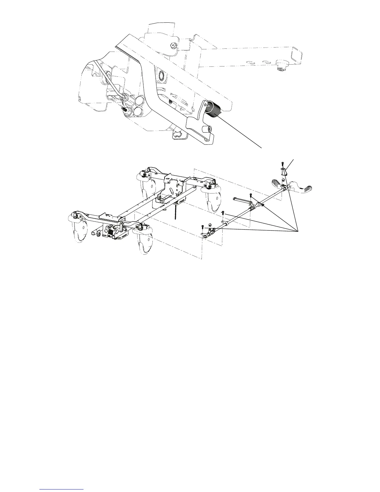
Torque item J
to 13 ± 2 ft-lb
FFiigguurree 66 –– RReeppllaaccee tthhee bbrraakkee rroodd -- ffoooott eenndd
SSiiddee ccoonnttrrooll bbrraakkee rroodd rreeppllaacceemmeenntt
TToooollss RReeqquuiirreedd::
• 1/2” socket
• 3/8” drive torque wrench (ft-lb)
• 3/8” drive ratchet
• Needle nose pliers
• Bungee cords
1. Raise the litter to the highest position.
2. Raise the siderails to the up and latched position.
3. Raise the base hood and support the base hood with bungee cords.
4. Apply the brake. Push on the product to make sure that the brake is locked.
5. Using needle nose pliers, remove the rue ring cotter (A) and clevis pin (B) that secure the side control brake assembly to
the side control brake rod link (Figure 7). Save the rue ring cotter and clevis pin.
6. Using a 1/2” socket and 3/8” drive ratchet, remove the four hex washer head screws (C) that secure the side control
brake rod assembly to the base assembly. Discard the assembly. Save the screws. When you reinstall the screws, use
a 3/8” drive torque wrench to torque the screws to 13 ± 2 ft-lb.
7. Reverse steps to install the supplied side control brake rod assembly.
0747-109-002 Rev A.3
23 EN