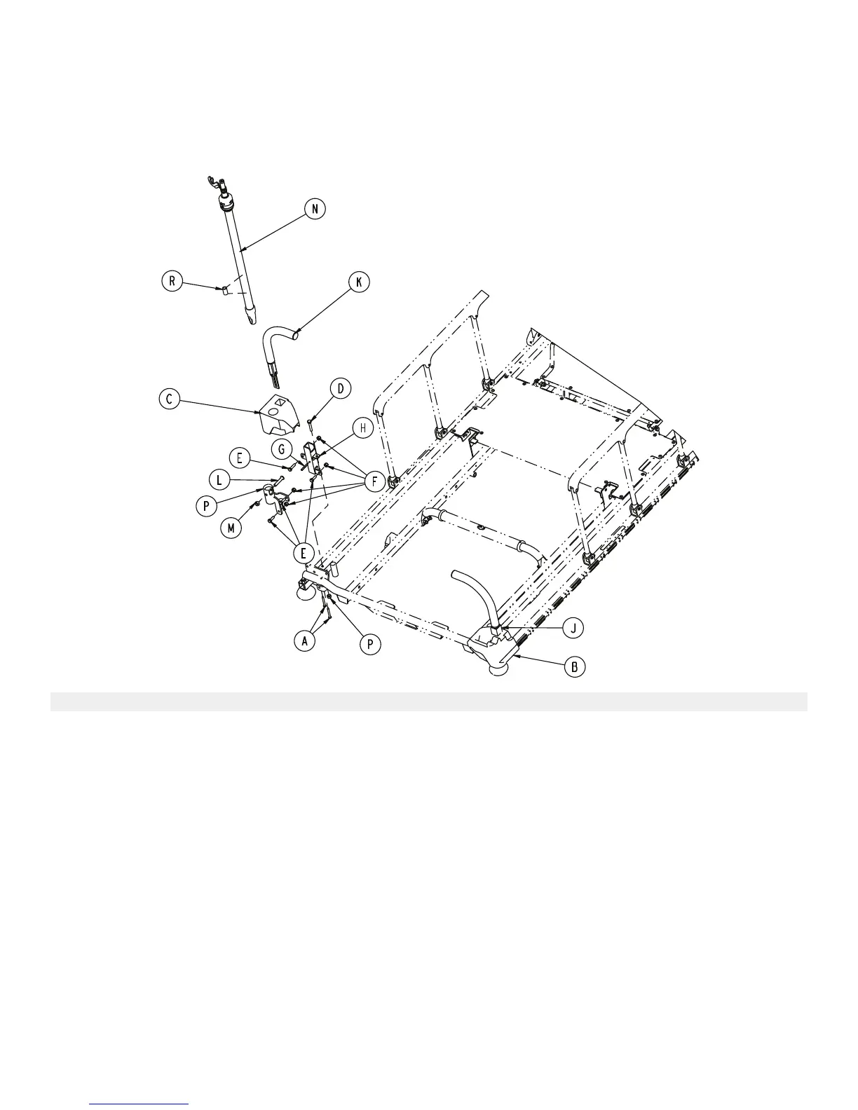
CCoorrnneerr ccoovveerr aasssseemmbbllyy wwiitthh ooppttiioonnaall ppuusshh hhaannddlleess aanndd ttwwoo--ssttaaggee IIVV
ppoollee
0744-035-025 Rev A (Head) (Reference only)
0744-035-075 Rev A (Foot) (Reference only)
IItteemm NNuummbbeerr NNaammee QQuuaannttiittyy
A 0023-283-000 Self-tapping screw 4
B 0742-201-236 Corner cover, slot 1
C 0742-201-237 Corner cover, hole 1
D 0003-047-000 Hex head cap screw 2
E 0003-050-000 Hex head cap screw 6
F 0016-028-000 Fiberlock hex nut 8
G 0026-012-000 Slotted spring pin 2
H 0748-254-004 Push handle socket, left 1
J 0748-254-006 Push handle socket, right 1
K 1211-351-010
Push handle assembly
(page 80) 2
L 0004-199-000 Button head cap screw 1
M 0016-036-000 Nylock hex nut 1
N 1211-210-010 Two-stage IVpole assembly 1
P 0748-259-103 IV pivot weldment 1
R 1001-259-042 IV plug 1
0747-109-002 Rev A.3
81 EN