0702-014-700 Rev-B 2008/04
www.stryker.com 3
A
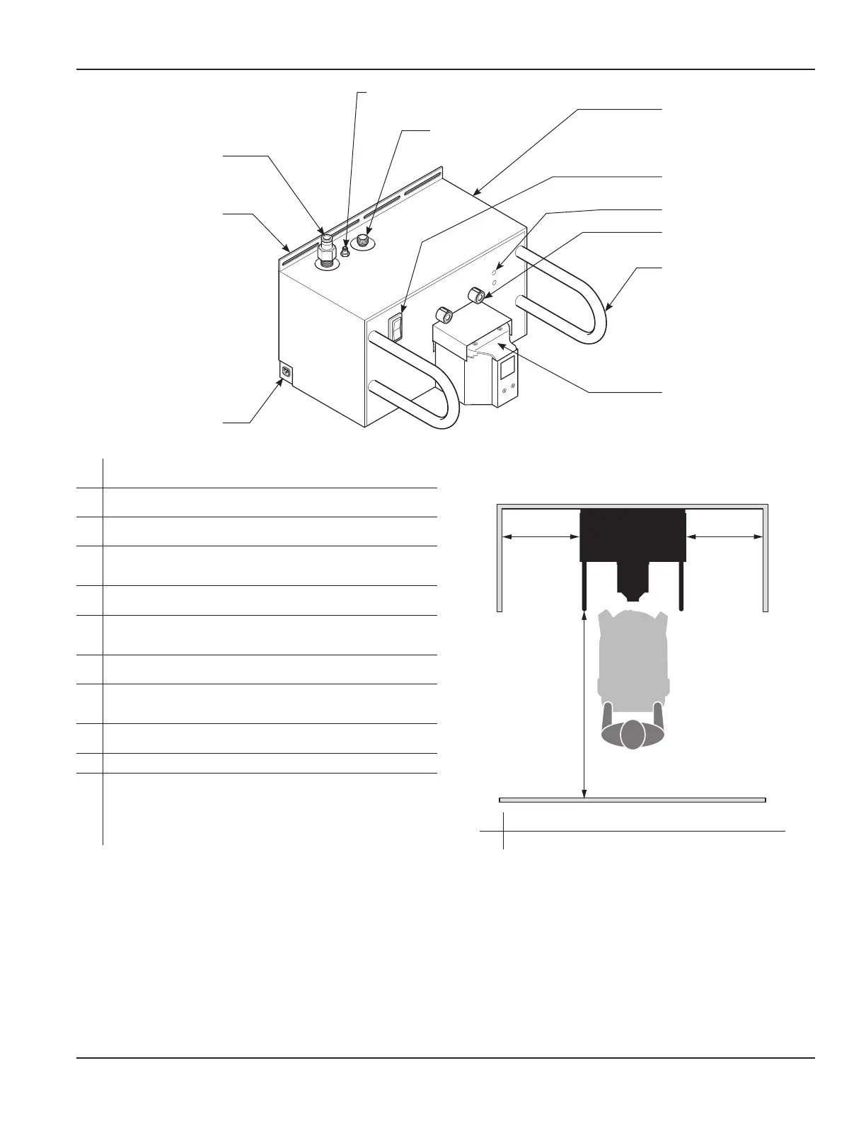
Power Cord Receptacle-Allowsfortheconnectionoffacilitypower
using the docker power cord.
B
Mounting Bracket-Usingmountinghardware,thebracketallowsfor
thepermanentinstallationofthedockertoaflatwallsurface.
C
Waste Outlet Port-Allowsforthedisposaloffluidwastefromthe
rover when the rover is connected to the docker.
D
Detergent Inlet Port-Allowsdetergenttoentertherover’sfluid
collectionsystemtofacilitatecleaningwhentheroverisconnectedto
the docker.
E
Water Inlet Port-Allowsfreshwatertoentertheroverwhentherover
is connected to the docker.
F
Ethernet and USB Ports-Theseportsarelocatedonthesidepanel
(notvisibleinillustration)andmaybeaccessedbyremovingacover.
AllowsforStryker-approvedsoftwareupgradesandmaintenance.
G
Power Switch-Thetoggleswitchallowsfortheapplicationor
removaloffacilitypower.
H
Infrared Communication Windows (two)-Allowsinfrareddata
transfer between the docker and rover. Data transfer is necessary
during the docking procedure.
I
Magnets (two)-Providesfortheautomaticphysicalalignmentand
connection of the rover to the docker.
J
Guides (two)-Facilitatesthealignmentoftherovertothedocker.
K
Power and Fluid Connectors-Whentheroverisconnectedtothe
docker, the rover receives power through a power connector from
thedocker.Twofluidconnectorsarealsopresent.Oneconnector
allowsfreshwatertoentertherover.Theotherconnectorprovidesfor
thedisposalofwastewaterfromtherover.Thefluidconnectorsare
locatedunderaspring-loadedcover.
Figure 1 Docking Station Feature Locations
Features
A
B
C
D
E
F
G
H
I
J
K
NOTE: See the Specificationssectionforelectricalpower,water,and
drainagerequirements.Seefigures1and2toensuretheinstallationarea
meetsutilityandspacerequirements.
A SideClearance 20inches[50.8cm]
B FrontClearance 48inches[121.9cm]
A A
B
Figure 2 Minimum Space Requirements

 Loading...


