-11-
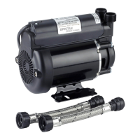
The pumps are supplied with a non-return valve which should be screwed directly into
the pump outlet port. The purpose of the valve is to limit back flow and pressure on the
pump and ensure discharge pipework is always primed with water. The pumps are also
supplied with an outlet adaptor which allows for a range of different pipework connections
as follows: G1 - G¾ male thread or 25/22 mm diameter bore hose. For best flow use the
largest pipe possible, small sizes will reduce performance. The pump should be installed
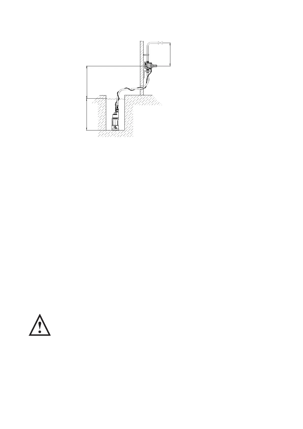
vertically and should be submerged at all times to avoid overheating of the motor. When
siting the pump ensure its base is raised slightly from the base of the sump reducing the
possibility of blocking the pump inlet filter with debris. The discharge pipework must be
independently supported to prevent forces being transferred to pump outlet branch.
If the pump is not to sit on the bottom of the sump or it is too deep, then it should be
suspended by a rope attached to the lifting eye located on top of the pump.
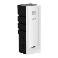
The pressure control module is supplied loose with the Diver pumps. The control
module is to be mounted remotely from the pump in a dry frost free enclosure or building
(Fig. 8). Ensure the water flow is in the direction of the arrows that are moulded onto the
pressure control module (vertically upwards).
The control module must be mounted in the vertical position and not mounted in any
other way (on its side for instance).
The pump must be wired to the control module as detailed in wiring diagram section.
RELEASE AND CONNECTION OF PUSH-IN FITTINGS (Surface Pumps only)
WARNINGS: (Push-In Connectors)
Do not use stainless steel, chrome or nickel plated pipe with Stuart
Turner push-in plumbing connections.
Do not introduce solder flux into the joint or surrounding area as
connectors will be attacked and may fail.
All solder joints should be completed and flux residues removed
before final connection to push-in connections, either on flexible hose
or pump head.
Do not allow contact with oil or cellulose based paints, paint thinners
or strippers, acid based descalents or aggressive cleaning agents.
Fig. 8
Max. 7 m
Max. 14 m
Typical Submersible
Boostamatic Installation
Max. 15 m