D19 MicVALVE
E1/4 Come in! Date printed: 9.2.2000
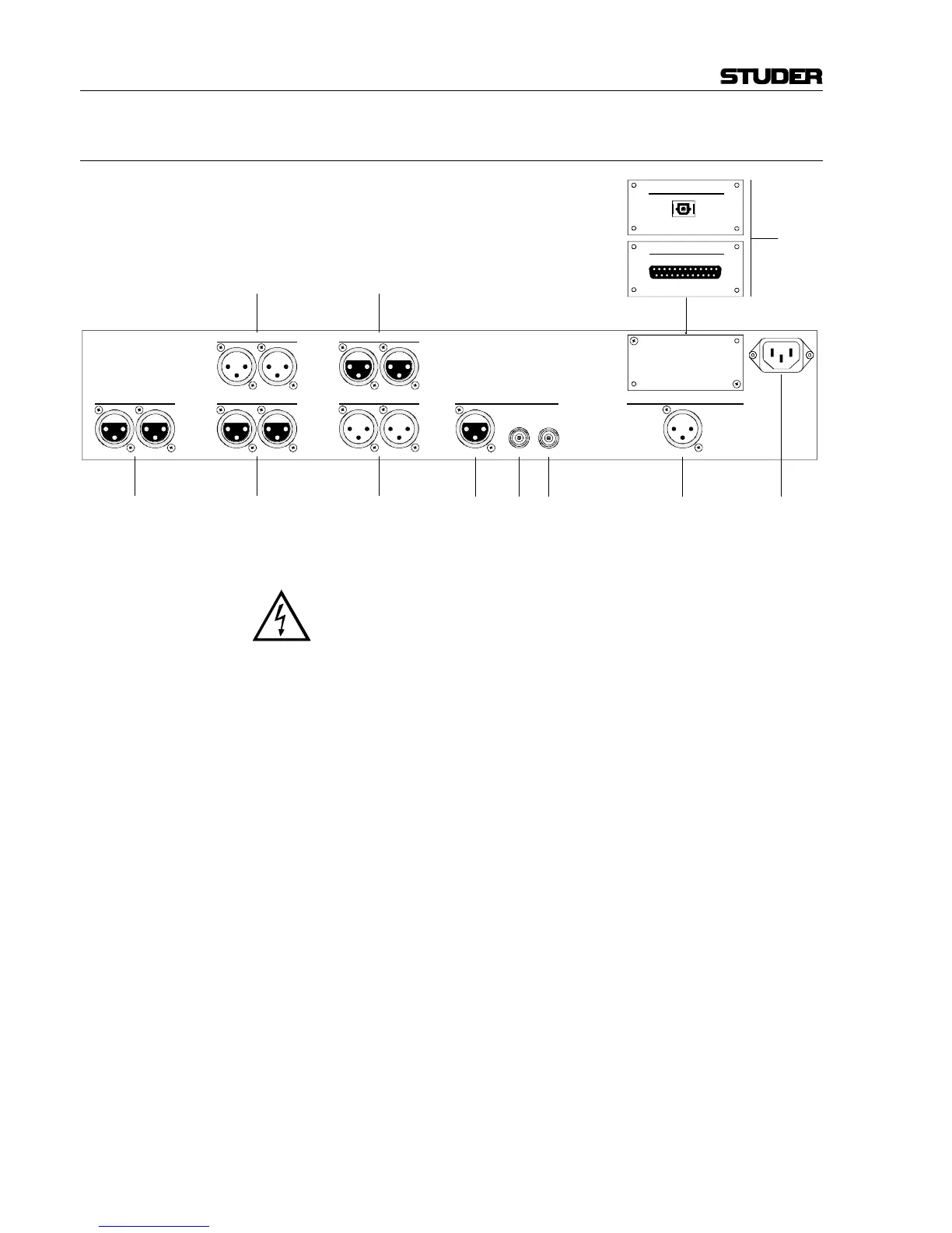
1.3.3 Connector Panel
[1] AC POWER Connector for socket IEC 320/C13.
Supply voltage range 100...240 V
AC
(without voltage selector); mains fre-
quency 50...60 Hz.
For connecting to the mains, please consult the Safety section at the very
beginning of this manual.
[2] MIC INPUTS Microphone inputs on female XLR connectors. Sensitivity for full-scale
input level of the A/D converter adjustable from –55 dBu to +20 dBu. Input
impedance 1 kΩ, transformer-balanced.
[3] LINE INPUTS Analog line inputs on female XLR connectors. Sensitivity for full-scale
input level of the A/D converter adjustable from –1 dBu to +24 dBu. Input
impedance 11 kΩ, transformer-balanced.
[4] LINE OUTPUTS Analog line outputs on male XLR connectors. Output impedance ≤ 20 Ω,
electronically balanced.
[5] AES IN Input for external synchronization via AES/EBU (female XLR connector).
[6] WCLK IN Input for external Word Clock synchronization (BNC connector, 75 Ω).
[7] WCLK OUT Output of the Word Clock Sync signal (BNC connector, 75 Ω).
[8] DIGITAL OUT AES/EBU output on male XLR connector, transformer-balanced. Output
impedance 110 Ω.
[9] INSERT SENDS Output of the insert point, on male XLR connectors. Output impedance
~50 Ω, electronically balanced.
[5] [6] [7] [8] [1][3]
[9]
[11]
f
INSERT SENDS INSERT RETURNS
MIC INPUTS SYNCHRONIZATION DIGITAL OUT
LINE OUTPUTSLINE INPUTS
R
L
RL
WCLK OUTWCLK INAES IN
R
L
R
LRL AES/EBU
[2]
[4]
[10]
m
TDIF-1
DIGITAL MCH OUT
OPTICAL OUT
DIGITAL MCH OUT
ff
fffff
m m
m m