D19 MicVALVE
Date printed: 9.2.2000 Additional Information E3/3
3.2 Block Diagrams
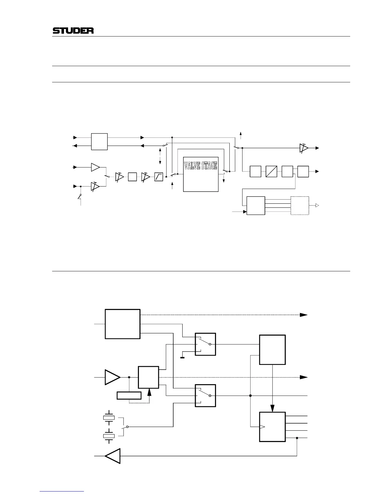
3.2.1 Global Audio Block Diagram
Only one channel shown; 48 V Phantom power, Mic/Line input, Level,
Phase inversion, High-pass filter, and the parameters of the switchable valve
stage can be set individually per channel, while Soft Clip is a global func-
tion.
Switch settings shown: VALVE OFF; INSERT ON and POST. Display
indication: «INS»
3.2.2 Synchronization Block Diagram
The Word Clock PLL which transforms up to 256 × f
s
is automatically
stopped if no word clock is applied. The quartz oscillators can be stopped
by the controller individually.
LINE
MIC
-14 dB
-10, 0...20 dB
48 V
0, 10...30 dB
Φ
Insert
module
SEND
RETURN
A
D
Soft
Clip
DSP
AES
TX
MCH
output
module
(optional)
ROUTING
SOUT12
SOUT34
SOUT56
SOUT78
PRE-INSERT
VALVE
POST-INSERT
PRE/POST
LINE OUT
(analog)
AES/EBU OUT
ADAT/TDIF OUT
(optional)
- Bass softener
- Angel zoom
- Valve drive
16.5 dBu
FS
FS
VALVE
STAGE
16.5 dBu
FS
FS
AES SYNC
Input
Word clock
Input
Disable
AES
Receiver
PLL
×256
Fs
select
256 Fs
select
Phase
control
Fs SEL
Divider
preset
A_UNLOCK
W_UNLOCK
256 Fs
64 Fs
2 Fs
Fs
32 Fs
Word clock
Output
44.1 kHz
48 kHz