STUDER Innotec
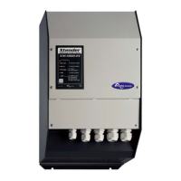
Xtender
2 V.3.2.0 User manual
6.2.4 Battery charger ........................................................................................................................... 2 1
6.2.5 Limiting the input current by limiting the charger current .................................................... 22
6.2.6 The inverter as source backup (“Smart Boost” function) ..................................................... 23
6.2.7 Input current controlled by input voltage............................................................................... 24
6.2.8 Battery protection ....................................................................................................................... 24
6.2.9 Xtender protection ..................................................................................................................... 24
6.2.10 Auxiliary contacts ................................................................................................................... 24
6.2.11 The real time clock ................................................................................................................. 25
6.2.12 Entry command (Remote control on/off) .......................................................................... 25
6.3 Multi-unit configurations ................................................................................................................. 25
6.3.1 Three-phase system .................................................................................................................... 26
6.3.2 Increasing the power by paralleling units ............................................................................... 26
6.3.3 Combined system ....................................................................................................................... 27
6.4 Accessories ....................................................................................................................................... 27
6.4.1 Control centre and display RCC-02/03 (remote control) .................................................... 27
6.4.2 BTS-01 temperature sensor ......................................................................................................... 28
6.4.3 Remote control Module RCM-10 .............................................................................................. 29
7 CONTROL .......................................................................................................................................... 29
7.1 Main on/off control ......................................................................................................................... 29
7.2 Display and control panel .............................................................................................................. 30
8 MAINTENANCE OF THE INSTALLATION ............................................................................................. 32
9 PRODUCT RECYCLING ...................................................................................................................... 32
10 EC DECLARATION OF CONFORMITY ................................................................................................ 33
11 COMMENTS OF APPENDIX DRAWINGS ............................................................................................ 34
12 DRAWING’S ELEMENTS (DC PART) .................................................................................................... 36
13 FIGURE ELEMENT'S (AC PART) ........................................................................................................... 37
14 ELEMENTS OF CONNECT CABINET (FIG 4A) ..................................................................................... 38
15 CONTROL AND DISPLAY PARTS FOR THE XTENDER (FIG. 4B) .......................................................... 39
16 MODEL IDENTIFICATION (FIG. 1B) .................................................................................................... 40
17 TABLE OF STANDARD CONFIGURATIONS ......................................................................................... 41
18 TECHNICAL DATA – XTH .................................................................................................................... 43
19 TECHNICAL DATA – XTM ................................................................................................................... 45
20 NOTES ................................................................................................................................................ 47