(Mar, 2012)
Compact CWE Series Installation, Operation & Maintenance Manual
ir Technology Systems, Inc.
2-2
close tolerance control of temperature and humidity.
The conditioned space should be well insulated and
include a vapor barrier. The installer should ensure
that the proper insulation rating is used based
on the design of the space, which was the basis
for the system selected. The following chart is a
recommended minimum R-value (thermal resistance)
to ensure optimum equipment operation.
STRUCTURE R-VALUE
Ceiling R-38
Wall R-21
Floor R-19
Door R-5
The vapor barrier is the single most important require-
ment for maintaining environmental control in the
conditioned space. The vapor barrier in the ceiling and
walls can be a polyethylene fi lm. Concrete walls and
fl oors should be painted with a rubber or plastic based
paint. Doors and windows should be properly sealed
and a door sweep used to minimize leakage. Outside
or fresh air should be kept to a minimum (as it adds to
the cooling, heating, dehumidifi cation and humidifying
loads), while still maintaining the requirement of the
Indoor Air Quality (IAQ) standard. Lack of attention to
these factors can cause erratic operation, unstable
room control and excessive maintenance costs.
2.3 Rigging
Compact CWE systems are designed to be kept in a
vertical position. Move the unit with a suitable device
such as a forklift, pallet jack, or roller bar and dollies.
A weight table is provided on the installation draw-
ing. The unit is shipped on a skid to facilitate moving
prior to installation. The unit should always be stored
indoors in a dry location prior to installation.
CAUTION
When moving the unit, it must be kept level
and in the vertical position to prevent damage.
2.4 Mounting/Placement
Compact CWE systems use a frame and panel
construction for unit rigidity. The cabinet design
allows full service accessibility without moving the
unit. Compact CWE systems that are not ducted
are designed to be located in the space to be
conditioned. Ducted units may be located inside or
outside the conditioned space, but are designed
to supply air to only one room. Compact CWE
systems are front accessible, which allows the unit
to be placed in a corner or between cabinetry. It is
recommended that the unit is positioned to obtain
optimum air circulation.
NOTE
Placement of the fl oor or ceiling registers is
important. If they are too close to the unit, the
supply air will be recirculated back to the unit
before it has circulated throughout the space.
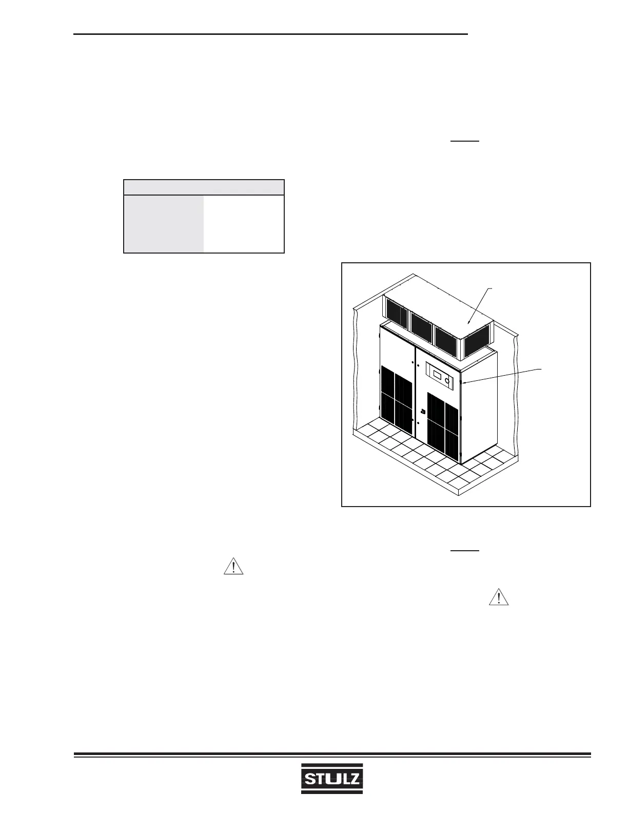
See Figures 6 & 7. The Compact CWE unit is de-
signed to be located on a raised fl oor (typically down-
fl ow) or directly on top of the fl oor (typically upfl ow).
Figure 6- Typical Installation Upfl ow
PLENUM BOX
ASSEMBLY
(OPTIONAL)
HINGED
DOOR
(BOTH SIDES)
NOTE
The equipment must be level to operate
properly.
CAUTION
Ensure the mounting surface is capable of sup-
porting the equipment. Before mounting the unit,
refer to the weight table provided on the installation
drawing. On some raised fl oor installations a fl oor
stand is required depending on the load capacity
of the existing raised fl oor (See Figure 7).