(Mar, 2012)
Compact CWE Series Installation, Operation & Maintenance Manual
ir Technology Systems, Inc.
2-5
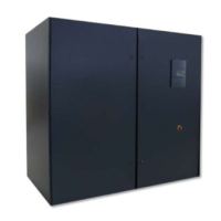
2.6.2 Deploying Underfl oor EC Fans
Compact CCD-2300 & CCD-2800 units may be
optionally equipped with “underfl oor” EC plenum fans
which may be lowered beneath a raised fl oor after
the unit is installed. The A/C unit is shipped with the
EC fans temporarily recessed inside the cabinet as
shown in Figure 11. The A/C unit must be installed on
a fl oor stand (purchased separately) with a minimum
height of 24 inches so the fans can be lowered.
Figure 11- EC Fans Recessed
CAUTION
Do not operate the unit with the fans in
the recessed position.
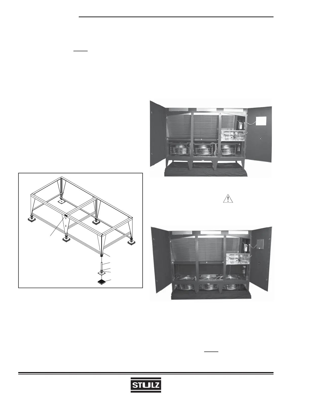
Figure 12- EC Fans Lowered
The fan assemblies are secured with shipping support
brackets as shown in Figure 13. The brackets safely
hold the fans in place during the period the A/C unit is
transported and installed.
NOTE
Only remove the shipping support brackets after
the A/C unit is mounted in it’s fi nal location.
2.6 Optional Equipment (Field Installed)
NOTE
Do not mount any optional equipment on the
unit access doors.
2.6.1 Floor Stand
Install the optional fl oor stand directly on the sub-fl oor,
ensuring the side with the “FRONT” label is facing the
same direction as the front of the precision A/C unit
(see Figure 10). Refer to the fl oor stand assembly
drawing for the dimensions required to cut the raised
fl oor. The fl oor stand is designed with adjustable legs,
allowing for leveling and overall height adjustment.
Refer to the fl oor stand assembly drawing for mini-
mum and maximum height adjustments. To adjust the
height, fi rst loosen the middle nuts on each leg. Next,
turn the top hex nuts to raise or lower the fl oor stand.
Once the fl oor stand is level and even with the raised
fl oor, lock all feet in place by tightening the middle
hex nuts against the top hex nuts.
Figure 10- Floor Stand Installation
THREADED ROD
MIDDLE HEX NUT
TOP HEX NUT
ISOLATION PAD
FLOOR STAND LEG
"FRONT" LABEL