(Mar, 2012)
Compact CWE Series Installation, Operation & Maintenance Manual
ir Technology Systems, Inc.
with your unit. Provide manual shut-off valves in both
the supply and return lines for servicing the unit and
for emergency isolation.
NOTE
A 60-mesh strainer is recommended to be
installed in the supply line. The strainer screen
should be cleaned periodically.
CAUTION
Chilled water cooling coils and associated
piping circuits are pressurized (up to 100 psi)
and sealed when the unit leaves the factory.
Before installing the interconnecting piping,
release the pressure via an available stem
valve or schrader valve prior to uncapping the
pipes.
If newly installed CW supply and return piping is
used, it is recommended that the piping system be
cleaned prior to connecting it to the unit. If solvents/
cleaning solutions are used, ensure they are
completely fl ushed from the piping before
connecting it. Failure to do so could result in
equipment problems
CAUTION
When installing and fi lling chilled water and
optional hot water reheat loops, all air must be
bled from the piping system.
NOTE
Chilled water lines should be insulated to
prevent condensation from forming on the pipes
if ambient dew point temperatures are higher
than the fl uid temperatures.
2.7.2 Condensate Drain
2.7.2.1 Gravity Drain
A drain line is installed to drain the condensate pan. If
an optional humidifi er is used, the drain line from the
humidifi er is typically connected to the condensate
drain line. The end of the drain line is clamped inside
the cabinet. The installer must install a customer
supplied drain hose to the end of the drain line to
remove water from the cabinet. See the installation
drawing provided with your unit for the size and
location of the condensate drain line.
2.7 Piping Connections
2.7.1 Chilled Water/Hot Water
Pipe connections for the chilled water and optional
hot water reheat piping are sweat connections. In
most cases, they terminate inside the cabinet except
units which are provided with pipe connections
protruding through the top of the cabinet.
When considering how to route the piping and wiring
for CCU (upfl ow) units furnished without top piping,
entry holes may be drilled through either the fl oor
of the cabinet or through a side panel. The SATS
installation drawing (furnished with your unit) shows
a recommended entry location. For special piping
requirements contact SATS for technical assistance.
For CCD (downfl ow) units, open areas for routing
the piping and wiring are available in the base of the
cabinet. Refer to the installation drawing provided
with your unit for the location of the openings.
If piping is brought into the side of the cabinet, ensure
adequate working space is available on that side or
if necessary cut a service opening into the adjacent
wall if the unit is installed in a corner. After the piping
is installed, seal the gaps between the pipes and the
entrance holes so air won’t leak around the pipes.
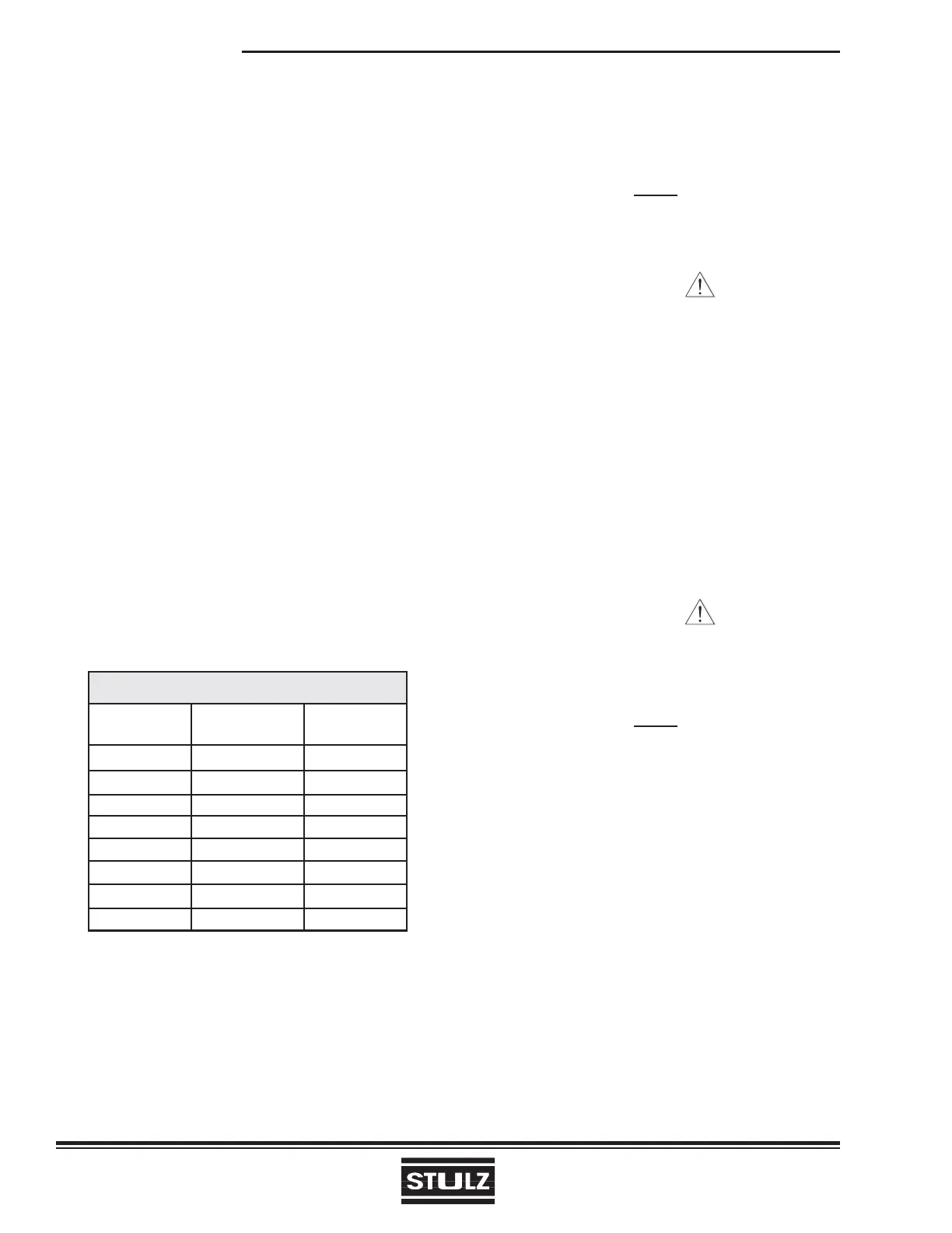
For pipe connection sizes, refer to the following table:
INLET/OUTLET PIPE SIZES
Chilled Water Hot Water
Model # (Inches O.D.) (Inches O.D.)
CCU/D-300 1 1/8” 7/8”
CCU/D-600 1 5/8” 7/8”
CCU/D-900 1 5/8” 7/8”
CCU/D-1200 2 1/8” 7/8”
CCU/D-1800 2 1/8” 7/8”
CCU/D-2300 2 1/8” (*or 2 5/8) 7/8”
CCU/D-2800 2 1/8” (*or 2 5/8) 7/8”
CCU/D-3600 3” 7/8”
*Special models requiring high CW fl ow are equipped with 2 5/8”.
Field piping is not necessarily the same size as the
units’ pipe connections. Piping should be sized to
match the system pressure drop and fl ow capacity,
and may require reducing fi ttings to match the
connection size on the air conditioner. An air vent and
several schrader valves are installed in the precision
A/C unit piping. Refer to the piping diagram supplied
2-9