(Mar, 2012)
Compact CWE Series Installation, Operation & Maintenance Manual
ir Technology Systems, Inc.
NOTE
In most cases the humidifi er drains (hot)
water into the condensate drain during normal
operation. As an option, a separate drain line
may be provided for the humidifi er.
The drain line must be located so it will not be ex-
posed to freezing temperatures. The diameter of the
drain line should be the full size of the connection.
NOTE
Pour some water into the condensate drain pan)
prior to start-up. This fi lls the trap and prevents
air from being drawn up the drain lines.
WARNING
Do not use chloride based water
conditioning additives in condensate drain
pans. This will cause corrosion to occur on
the coil fi ns.
2.7.2.2 Condensate Pump
An optional condensate pump is normally factory
installed. The drain connection is typically a 1/2”
copper tube. See the installation drawing provided
with your unit for the location of the pump and for the
size of the drain connection.
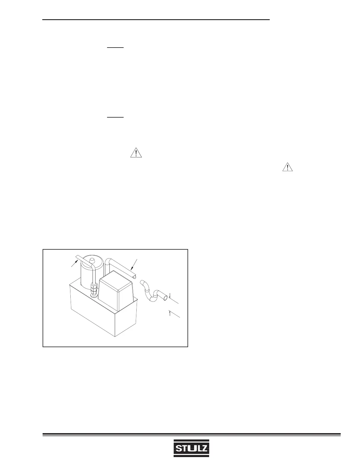
INLET 7/8" OD
OUTLET 1/2" OD
NOTES:
1. MIMIMUM HEIGHT IN INCHES.
2. P-TRAP MUST BE LOCATED IN THE INLET SIDE OF PUMP WHEN FIELD INSTALLED.
2.00
SEE NOTE 1
SEE NOTE 2
Figure 16- Condensate Pump
If an optional fi eld installed condensate pump is used,
a p-trap must be installed to allow proper condensate
drainage (see Figure 16). The height of the trap must
be a minimum of 2 inches on standard systems to
ensure proper water drainage. The condensate pump
discharge line should be 1/2 inch O.D. (maximum)
copper pipe to prevent excessive back fl ow to the
condensate pump.
2-10
2.7.3 Humidifi er
Compact CWE systems utilize an electrode steam
humidifi er. In most cases the humidifi er empties into
the condensate drain line during the fl ush/drain cycle.
As an option, the drain for the humidifi er may have a
separate connection. Refer to the installation drawing
provided with your unit for the size and location of the
connection.
A water supply line for the humidifi er must be con-
nected to the end of the copper tubing provided by
the factory. Refer to the installation drawing provided
with your unit for the size and location of the connec-
tion. The humidifi er requires normal tap water for the
water supply. If the supply water is high in particulate,
an external fi lter may be needed.
CAUTION
Do not use de-mineralized water.
Refer to the humidifi er operator’s manual, supplied
with the equipment, for complete manufacturer’s
information on the humidifi er and the supply water
recommendations.